3 limit switch cable (for xsel-j/k) cb-x-lc ƒƒƒ – IAI America FS User Manual
Page 25
19
1.4.3
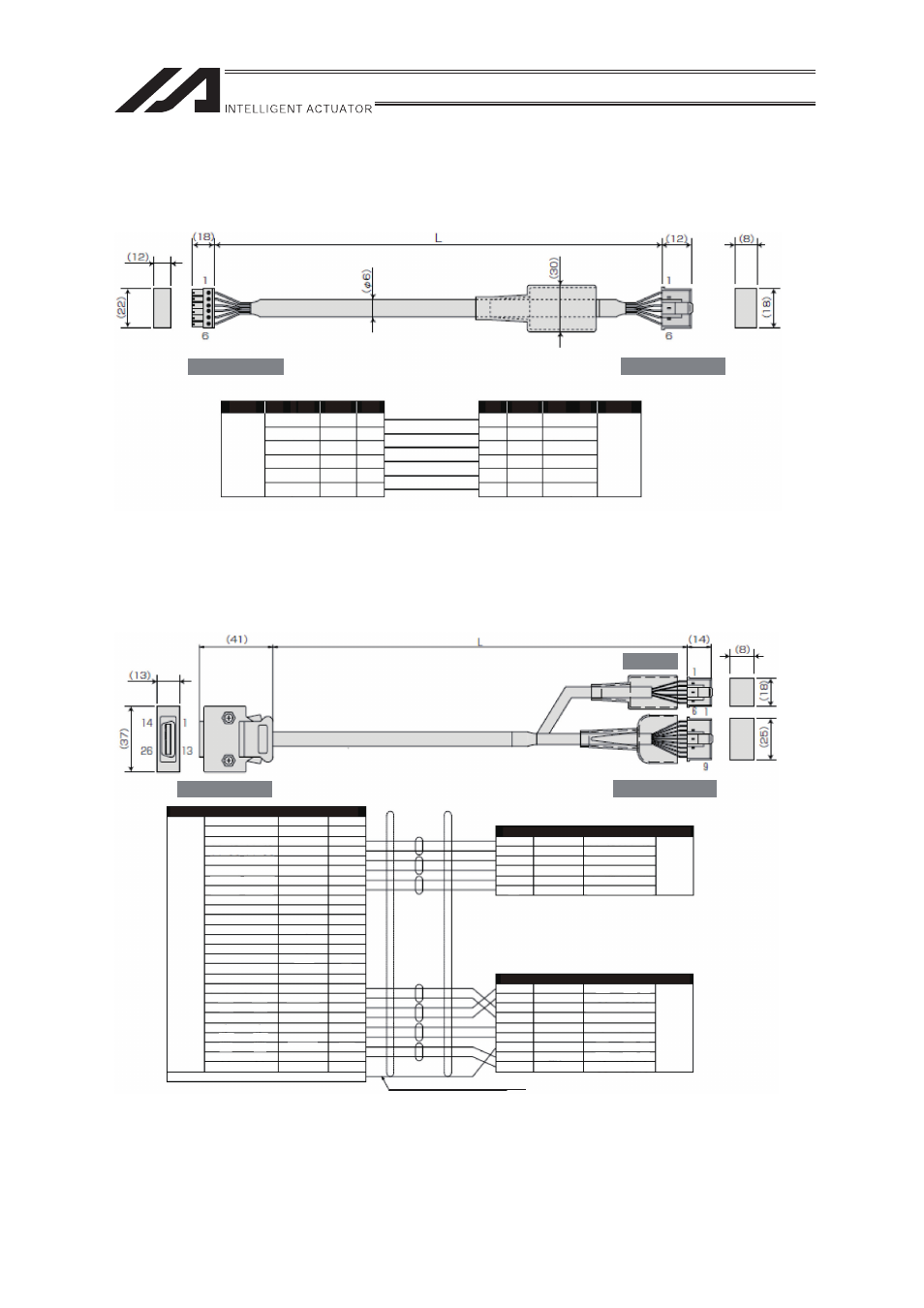
Limit Switch Cable (For XSEL-J/K)
CB-X-LC
ƑƑƑ
(Front View)
(Front View)
Wiring
AWG24
No.
6
5
4
3
2
1
Signal
24VOUT
N
LS
CREEP
OT
RSV
Color
Sky Blue
Pink
Light Green
Orange
Gray
1B/Sky Blue
Note) 1B indicates one black dot mark.
No.
1
2
3
4
5
6
Signal
24VOUT
N
LS
CREEP
OT
RSV
Color
Sky Blue
Pink
Light Green
Orange
Gray
1B/Sky Blue
Wiring
AWG24
(Solderless)
Controller Side
Mechanical Side
1.4.4 Encoder
Cable
(For XSEL-P/Q, SSEL, SCON and LS equipped type connection)
CB-X1-PLA
ƑƑƑ
(Front View)
LS Side
The shield is clamped to the hood
Ground wire and braided shield wires
(White/blue in cable color indicates the colors of line/insulator.)
Wiring
Color
Signal
No.
10
11
12
13
26
25
24
23
9
18
19
1
2
3
4
5
6
7
8
14
15
16
17
20
21
22
Signal
-
-
E24V
0V
LS
CREEP
OT
RSV
-
-
-
A+
A-
B+
B-
Z+
Z-
SRD+
SRD-
BAT+
BAT-
VCC
GND
BKR-
BKR+
-
-
-
White/Blue
White/Yellow
White/Red
White/Black
White/Purple
White/Gray
-
-
-
-
-
-
-
-
-
Orange
Green
Purple
Gray
Red
Black
Blue
Yellow
-
AWG26
(Soldered)
No.
1
2
3
4
5
6
E24V
0V
LS
CREEP
OT
RSV
Color
White/Blue
White/Yellow
White/Red
White/Black
White/Purple
White/Gray
No.
1
2
3
4
5
6
7
8
9
Signal
BAT+
BAT-
SD
SD
VCC
GND
FG
BK-
BK+
Color
Purple
Gray
Orange
Green
Red
Black
Drain
Blue
Yellow
Wiring
AWG26
(Solderless)
Wiring
AWG26
(Solderless)
Controller Side
Mechanical Side