Securitron iMXDa_iEXDa INSTALLATION User Manual
Page 6
P/N 500-22175
Page 6
Rev. B, 04/11
Electrical Wiring
All wiring to the installed unit is made to the main terminal strip on the PC board inside the wire
access compartment. See Appendix B for wire gage size calculations. Further user-specific
(control) wiring connections are described in Section 6.3 - Control Wiring.
Power Supply Connections
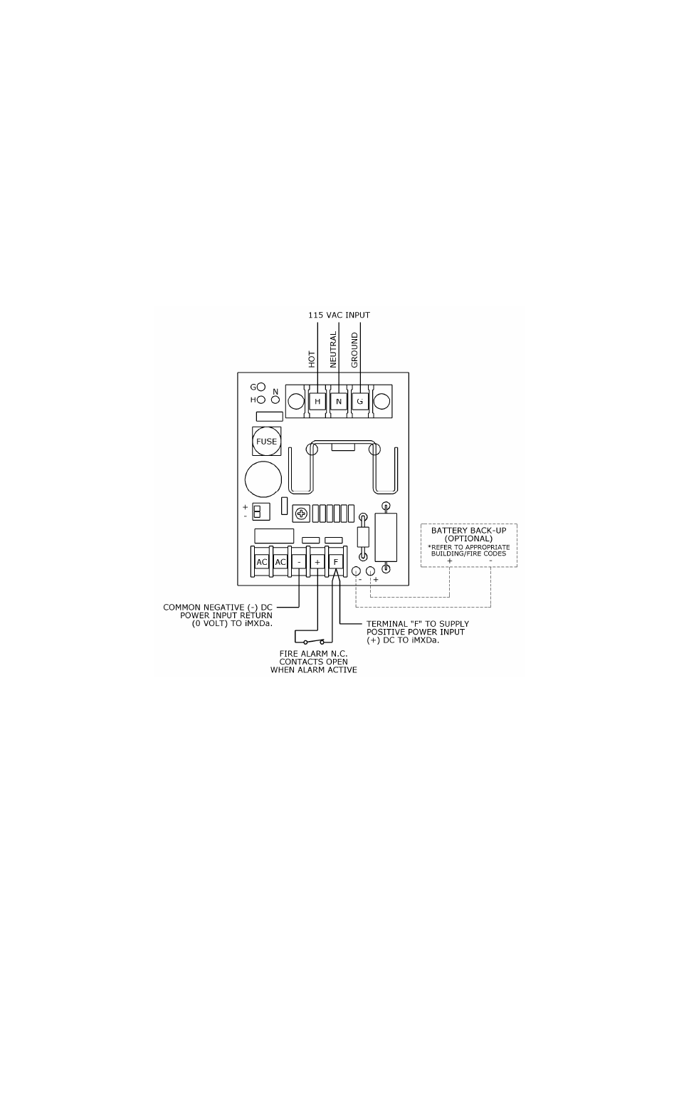
Figures 7, 8 and 9 illustrate the proper electrical wiring required for connecting the
iMXDa/iEXDa to various Securitron power supplies, for 1 Amp see Figure 7 for the larger 2 to 15
Amp Securitron power supplies utilizing the CCS-4 or CCS-8 see Figures 8 and 9.
ALWAYS REFER TO THE MANUFACTURER’S PRODUCT MANUAL FOR PROPER
CONNECTION AND IMPLEMENTATION OF THE POWER SUPPLY BEING USED
BATTERY BACK-UP IS NOT ALLOWED BY BUILDING CODES FOR INSTALLATIONS
WHICH REQUIRE THE LOCK TO RELEASE THE DOOR UPON LOSS OF POWER
(SEE APPENDIX D)
Figure 7
Connections for 1 Amp Power Supply (BPS-12-1/BPS-24-1)
- ASB_Series (2 pages)
- ASCWB-DM62CL (4 pages)
- CWB_Series (2 pages)
- EASB_Series (4 pages)
- GDB (2 pages)
- HHD (6 pages)
- IK_Series (3 pages)
- M34R_Series (10 pages)
- M370 (16 pages)
- M38 (L, S and LS with D and T Options) (14 pages)
- M38 T UPGRADE (2 pages)
- M380BD_C_C2_X MAGNALOCK_Series (20 pages)
- M670 (16 pages)
- M680BDCX (16 pages)
- M32 (16 pages)
- Z-32 (2 pages)
- ZA-32 (3 pages)
- UHB (2 pages)
- TJ-38 (7 pages)
- TDK-1 (1 page)
- SWB-03 (2 pages)
- SMLS_SMSS (4 pages)
- SAM2C-24 (1 page)
- SAM2-24 (11 pages)
- SAM (16 pages)
- 32 REPLACEMENT STRIKE (1 page)
- UNL-12 UNLATCH (10 pages)
- STK-1 (2 pages)
- MUNL-12 (11 pages)
- MM15-TS (1 page)
- MM15 Z-Bracket_Series (1 page)
- MM15 (2 pages)
- Blind Nut (1 page)
- FSUNL_Series (2 pages)
- SCL-12 (4 pages)
- MCL-24 (8 pages)
- SWK (2 pages)
- SPK (2 pages)
- SASM KIT STRIKE (1 page)
- GL1 Quick Start (1 page)
- GL1 Install (10 pages)
- FMK-SW (7 pages)
- BPSS-10 (7 pages)
- PB5E (2 pages)
- PB5 (2 pages)