Tank leak sensors, models jt-2p and jt-2v – Ronan X76CTM User Manual
Page 34
33
TANK LEAK SENSORS
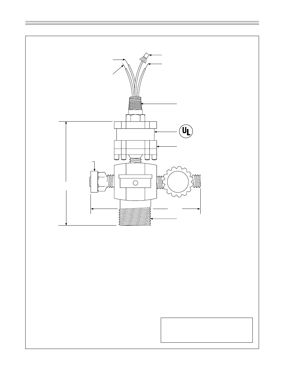
MODELS JT-2P & JT-2V
RED (CAPPED WIRE)
1 in. MALE NPT
LISTED 48RO
5.00 in.
6.25 in.
RELIEF
VALVE
PRESSURE SWITCH
1/2 in. NPT ELECTRICAL
CONNECTION
GREEN
GREEN
GREEN
®
INSTALLATION INSTRUCTIONS
Install the JT-2P Positive Pressure Leak Sensor or
JT-2V Positive Vacuum Leak Sensor on the tank
interstice riser. All other tank ports must be sealed
with #150 class pipe fittings. Teflon paste type
sealer is suggested for all threaded joints.
Provide electrical conduit, two each #18 AWG
wires to sensor input terminals of the Models
X76S, X76VS, X76LVC, X76LVCS, X76ETM, or
X76CTM tank monitors. Contact the brown and
blue sensor wires (N.O. position). Intrinsically safe
wiring must be in a dedicated conduit only. No 115
Vac or other wiring is allowed in the same conduit.
Pressurize the tank interstice with compressed air
or nitrogen, (DO NOT USE OXYGEN), or evacuate
the tank interstice through the JT-2P or V fill and
relief valve manifold (provided with the sensor) to
2.9 psig or 10 inches Hg. When the pressure or
vacuum has been applied, the system alarm will
return to normal.
NOTE:
When filling the tank annulus with com-
pressed air or nitrogen, the sensor fill and relief
manifold MUST be used. Never exceed 3 psig or
the tank warranty may be void.
WARNING:
The red wire, (N.C. position) MUST be
capped off to prevent a short circuit to ground.
NOTE:
Reference Ronan Engineering
Drawing Number X76B556