Figure 3 – Reese 56006 OUTBOARD CUSTOM QUICK INSTALL KIT User Manual
Page 3
©
2012 Cequent Performance Products, Inc.
Rev. B
56006N
2/28/12
3
17. In row 2 Install the 1/2” x 2 inch carriage bolts with the U-shaped spacer to be located in the corrugation between the box and the
mounting rail or between box and frame bracket (8) & (9). This insures a metal to metal contact and to prevent crushing the bed
corrugation. Attach with spacers, washers, and hex nuts as per the illustrations and tighten snug to keep the mounting rail from moving.
18. After fully installing the custom attachment brackets, tighten the fasteners in the following sequence. Note: Torque all ½ inch
hardware to 72 ft-lbs torque all 5/8” hardware to 150 ft. lbs. First torque the mounting rails to the frame brackets (8) & (9) and
then torque the frame brackets (8) & (9) to the truck frame.
19. Reinstall the Multi-Thread U-nuts, Axle Bumpers and the Axle Bumper Hex Bolts back onto the truck frame if removed.
20. Reinstall spare tire and inner plastic wheel well liner of removed.
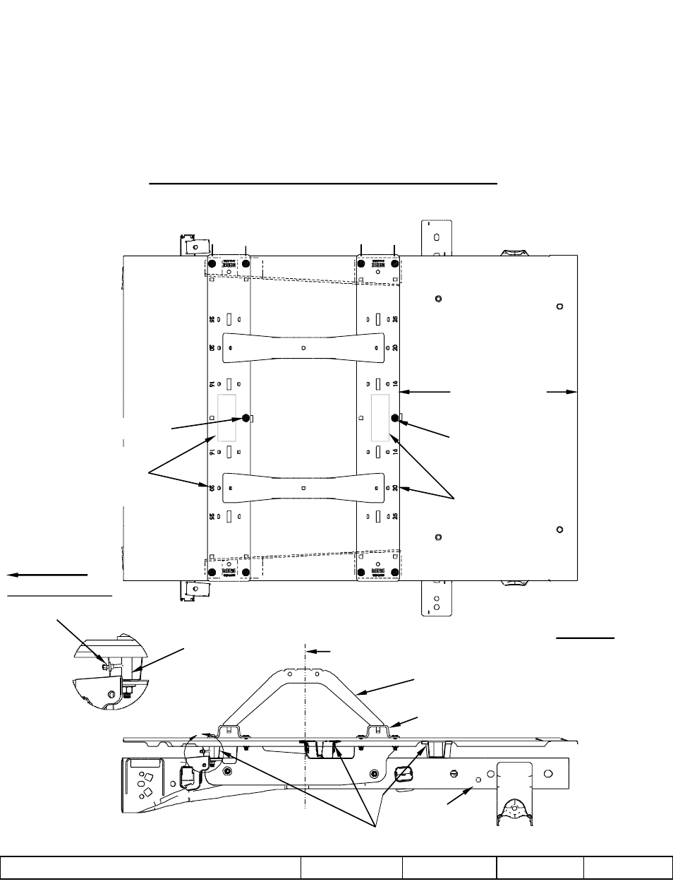
FRONT OF VEHICLE
DIMENSIONS SPECIFIC FOR RAIL KIT 30153
A
.
DRILL AND BOLT LOCATIONS
26 3/16”
5.5’, 6.6’ & 8’ bed
CENTER BOLT
CENTER BOLT
RO
W
1
RO
W
2
ROW
4
ROW
3
C OF HITCH AND AXLE
L
MOUNTING RAIL
BUSHING
HITCH SUPPORT / SLIDER/ GOOSE
(HITCH SUPPORT SHOWN)
FRAME
TRUCK BED SUPPORTS
Figure 3
REESE DECAL AND
RATING NUMBERS
FACING REAR OF
TRUCK BED
REESE DECAL AND
RATING NUMBERS
FACING FRONT OF
TRUCK BED
DETAIL A
STACK
WASHERS