Figure 11d, Figure 11a, Figure 11b – Reese 30144 18K ELITE SERIES User Manual
Page 7: Figure 11c
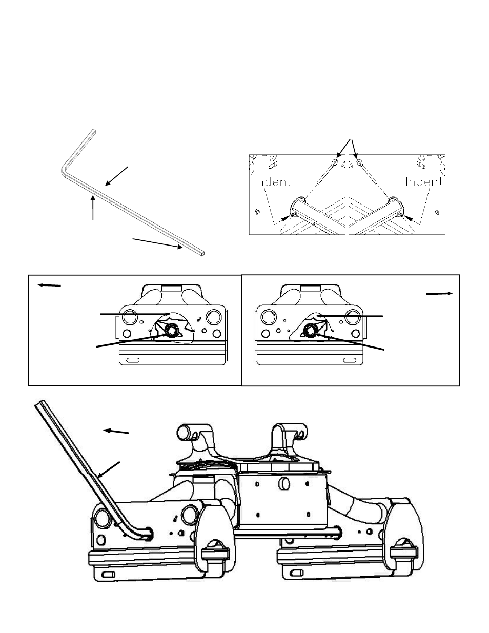
4. Assemble the slider handle and the connector tube, minus the cotter pins. The cotter pin holes should all be
on the same sides.
See Figure 11a
. Make sure the lock cams inside the slider assemblies are orientated in
the same direction, towards the front of the truck.
See Figure 11b
. If not, pull up on the “jaw” mechanism
and rotate them until they do. Slide the slider handle assembly through the driver’s side slider assembly.
The slider handle must be in the same orientation as the lock cams in the slider assembly (handle points
towards front of truck).
See Figure 11b & 11c
. Insert the cotter pins into the slider handle assembly (cotter
)
g
&
p
y (
pins should go into the holes that are nearest the slider assemblies).
See Figure 11d
. The indents on both
slider assemblies must be aligned to each other and also aligned to the holes in the slider handle and
connector tube.
See Figure 11d
. Do not put slider handle grip on slider handle yet.
Slider Assembl Handle
Cotter pins
Slider Assembly Handle
Cotter Pin Holes
Figure 11d
“Jaw” Mechanism
“Jaw” Mechanism
Figure 11a
FRONT OF TRUCK
FRONT OF TRUCK
Driver’s Side Slider Assembly cut away view
Passenger Side Slider Assembly cut away view
Lock Cam
Must point towards
front of truck
Lock Cam
Must point towards
front of truck
Jaw Mechanism
Jaw Mechanism
Figure 11b
FRONT OF TRUCK
Slider Handle
Assembly
30144N– 05JUL10A PCN13292 ©2010 CEQUENT PERFORMANCE PRODUCTS, INC.
Litho in USA
7
For Kit 30144
Figure 11c