Figure 24, Figure 25, Figure 26 – Reese 30144 18K ELITE SERIES User Manual
Page 14: Move freely in the system
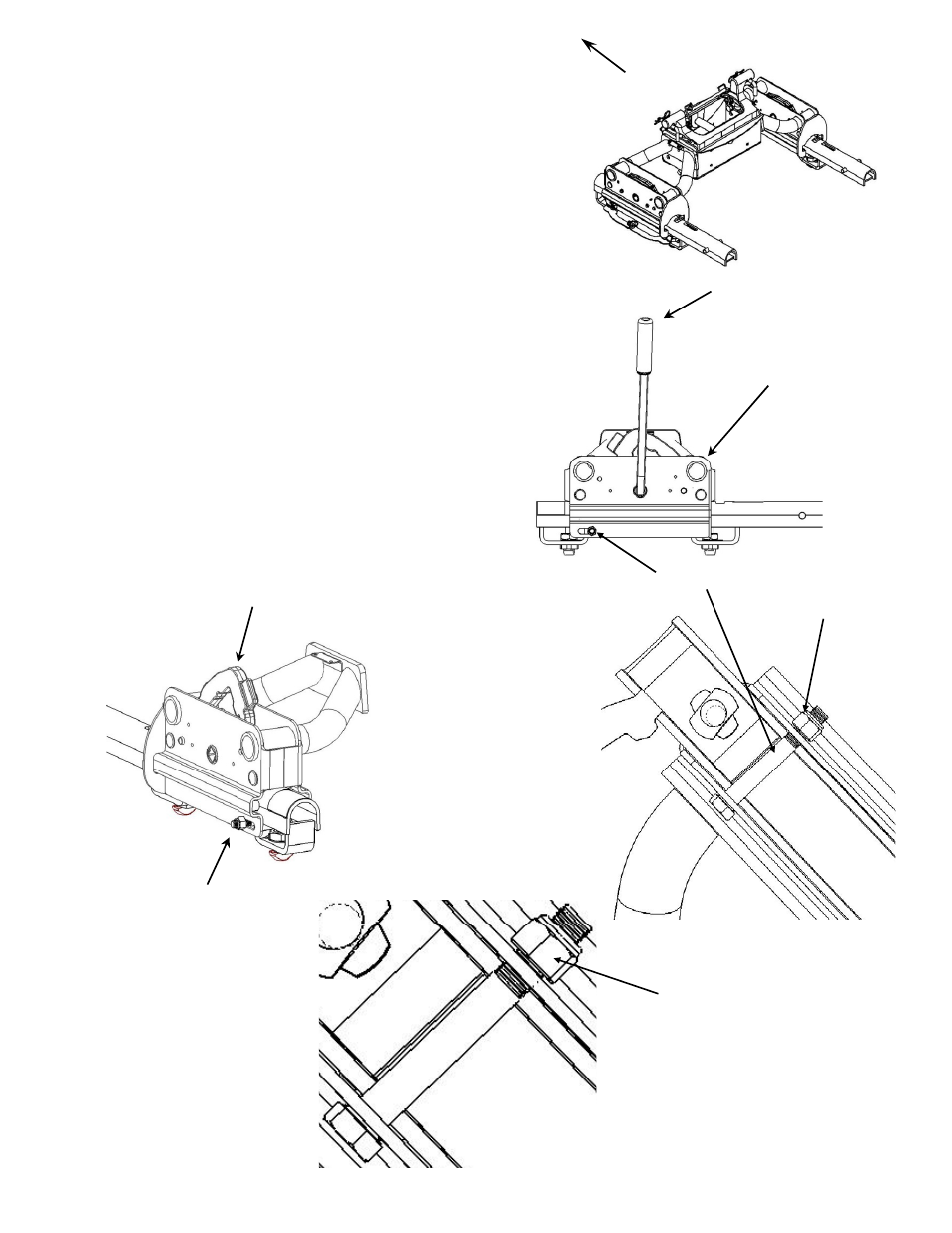
18.
Slide the entire slider assembly onto the slider
rails.
See Figure 24
. This is accomplished by
rotating the slider handle into the unlocked
position,
See Figure 25
. It may be necessary
to lift the “Jaw” Mechanism by hand when
t ti
th
lid
bl
th
lid
il
Front of Truck
starting the slider assembly on the slider rail.
See Figure 26
.
19. Install 1/2” bolts and 1/2” lock nuts onto both
slider assemblies.
See Figures 1, 25, & 26
.
Lock nut must be installed to the outside of
the system. A maximum of 3 threads MUST
be showing. Do not torque. See lock nut
detail below.
Figure 24
Slider Handle in
Unlocked Position
20.
Rotate the handles in the anchor assemblies
to the unlocked position and lift the entire
slider assembly and slider rails out of the
pucks. This is a precautionary measure to
insure that the hitch is assembled
correctly. If your hitch does not lift out of
the pucks repeat steps 7-11 on page 8-10.
21.
Replace the entire slider assembly and slider
il i t
k
ith ll h
dl
i
l
k d
Slider Assembly in
Towing Position
Figure 25
rails into pucks with all handles in unlocked
position. Rotate the handles to the locked
position, and place lynch pins through anchor
handle holes.
See Figure 19
.
“Jaw” Mechanism
1/2”
Lock
Nut
See detail below
1/2”
Bolt
½” Lock Nut –
Nut MUST be installed
Figure 26
To the outside of system for
System to work properly..
Lock nut to be installed
to the OUTSIDE of the
slider. DO NOT
TORQUE. Bolt MUST
move freely in the
30144N– 05JUL10A PCN13292 ©2010 CEQUENT PERFORMANCE PRODUCTS, INC.
Litho in USA
14
For Kit 30144
move freely in the
system.