Teledyne LGA-3500 - Laser Gas Analysis system User Manual
Page 28
Installation Model
3500
Teledyne Analytical Instruments
14
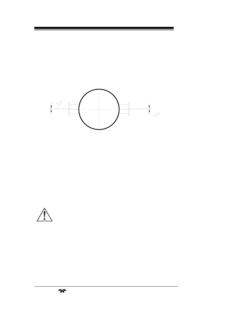
to have a limited coaxial offset between them. When welding the two
welding flanges the offset angle between their axes must be held to less
than 4°. Typically, the two welded flanges are positioned horizontally on
the gas flow pipe well across the pipe diameter As Shown in Figure 3-2.
Figure 3.2: Allowed offset for welded flanges
3.3.2 Installing Instrument Flanges
After welding the flanges, the Model 3500 probes can be installed.
Before installing, apply a lubricant to all the screw connections. To
make adjustments easier it is suggested that you use the adjusting aid
tools available from TAI
(P/N XXXXX)
. These include a visible light
laser pen and a scaled target for alignment.
WARNING: POWER TO THE SYSTEM MUST BE OFF DURING
THE INSTALLATION OF THE TRANSMITTER AND
RECEIVER UNITS. DO NOT CONNECT OR SWITCH
ON THE POWER SUPPLY AT THIS STAGE. THE
LASER BEAM IS INVISIBLE AND CAN CAUSE EYE
DAMAGE.
Mount the two instrument flanges onto the welded welding flanges
with 8 M16 bolts (with spring washer and plain washer) and 2 O-rings.
Raise the instrument flanges to the same height as the welded flanges,
then tighten the 8 M16 bolts to about half tight to make sure that the O-
rings are sealing. Typically the distance between the instrument flange
and the welding flange is around 3mm. See Figure 3.3.