Experiment 2: reflection, Equipment needed, Purpose – PASCO WA-9316A Complete Microwave Optics System User Manual
Page 9: Procedure
013-13906B
Experiment 2: Reflection
9
Experiment 2: Reflection
Equipment Needed:
Purpose
This experiment explores the relationship of reflected microwaves to incident microwaves when the incident microwaves
encounter a flat reflector at some angle measured from the normal of the reflector.
Procedure
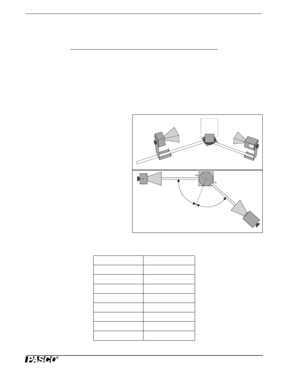
1. Arrange the equipment as shown in Figure 2.1
with the Transmitter attached to the fixed arm of
the Goniometer. Be sure to adjust the Transmitter
and Receiver to the same polarity; the horns
should have the same orientation as shown.
2. Plug in the Transmitter and turn the Receiver
INTENSITY selection switch to 30X.
3. The angle between the incident wave from the
Transmitter and a line normal to the plane of the
Reflector is called the Angle of Incidence (see Fig-
ure 2.2). Adjust the Rotating Component Holder
so that the Angle of Incidence equals 45°.
4. Without moving the Transmitter or the Reflector,
rotate the movable arm of the Goniometer until the
meter reading is a maximum. The angle between
the axis of the Receiver horn and a line normal to
the plane of the Reflector is called the Angle of
Reflection.
5. Measure and record the angle of reflection for each of the angles of incidence shown in Table 2.1.
Item
Item
Transmitter
Goniometer
Receiver
Metal Reflector
Rotating Component Holder
Table 2.1: Data
Angle of Incidence
Angle of Reflection
20°
30°
40°
50°
60°
70°
80°
90°
Figure 2.1: Equipment Setup
Figure 2.2: Angles of Incidence and Reflection
NOTE: At various angle set-
tings the Receiver will detect
both the reflected wave and the
wave coming directly from the
Transmitter, thus giving mis-
leading results. Determine the
angles for which this is true and
mark the data collected at these
angles with an asterisk (“*”).