Questions – PASCO WA-9316A Complete Microwave Optics System User Manual
Page 32
Experiment Guide
Experiment 12: Bragg Diffraction
32
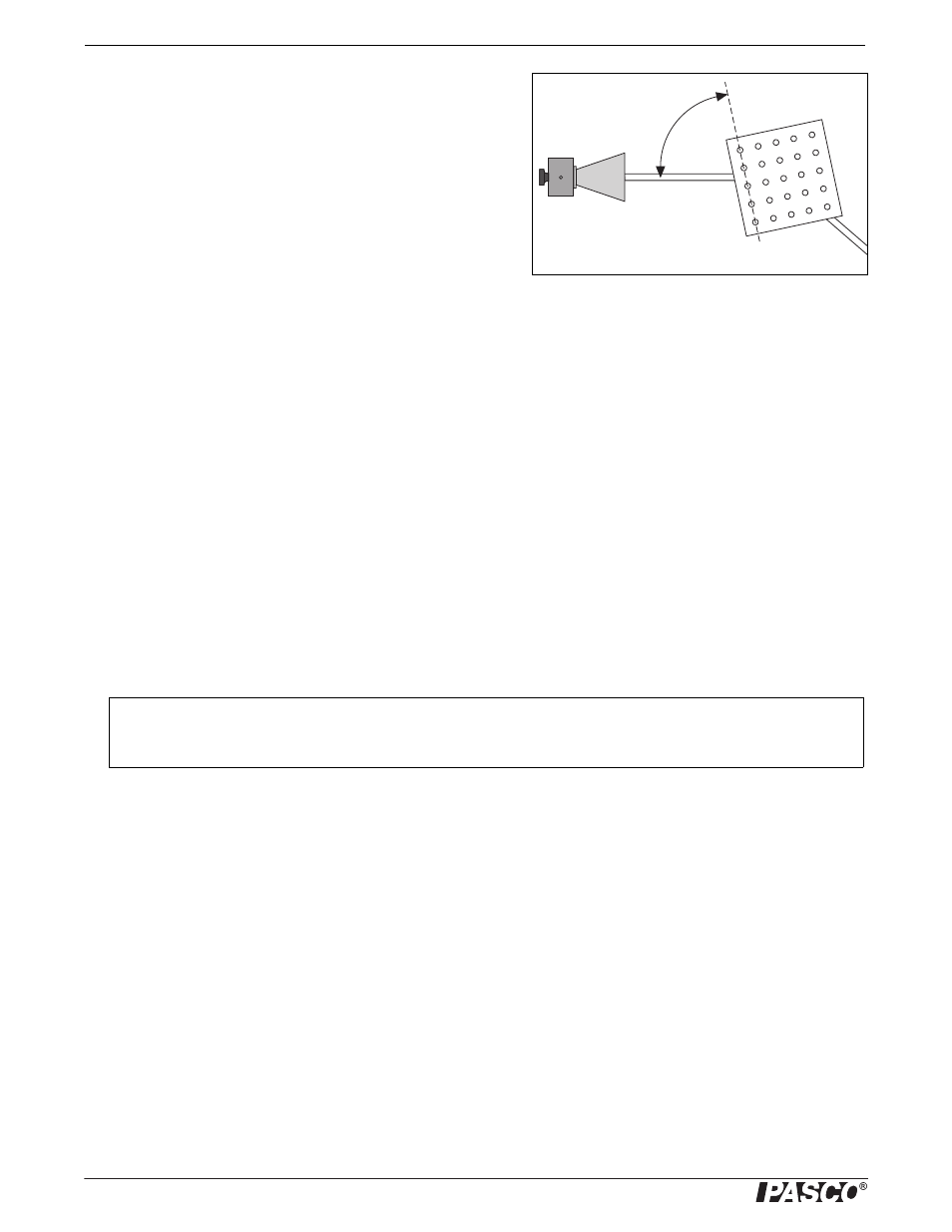
3. Rotate the crystal (with the rotating table) one degree clockwise
and the Rotatable Goniometer arm two degrees clockwise. Record
the grazing angle of the incident beam and the meter reading. (The
grazing angle is the complement of the angle of incidence. It is
measured with respect to the plane under investigation, NOT the
face of the cube; see Figure 12.3.)
4. Continue in this manner, rotating the Goniometer arm two degrees
for every one degree rotation of the crystal. Record the angle and
meter reading at each position. (If you need to adjust the INTEN-
SITY setting on the Receiver, be sure to indicate that in your
data.)
5. Graph the relative intensity of the diffracted signal as a function of the grazing angle of the incident beam. At what angles
do definite peaks for the diffracted intensity occur?
6. UUse your data, the known wavelength of the microwave radiation (2.85 cm), and Bragg’s Law to determine the spacing
between the (100) planes of the Bragg Crystal. Measure the spacing between the planes directly, and compare with your
experimental determination.
7. If you have time, repeat the experiment for the (110) and (210) families of planes.
Questions
1. What other families of planes might you expect to show diffraction in a cubic crystal? Would you expect the diffraction to
be observable with this apparatus? Why?
2. Suppose you did not know beforehand the orientation of the “inter-atomic planes” in the crystal. How would this affect the
complexity of the experiment? How would you go about locating the planes?
Grazing Angle
Figure 12.3: Grazing Angle
The Bragg Diffraction Experiment was developed by Dr. Harry Meiners of Rensselaer Polytechnic Institute.