Experiment 4: refraction through a prism, Equipment needed, Introduction – PASCO WA-9316A Complete Microwave Optics System User Manual
Page 15: Purpose, Procedure, Equipment needed: introduction
013-13906B
Experiment 4: Refraction Through a Prism
15
Experiment 4: Refraction Through a Prism
Equipment Needed:
Introduction
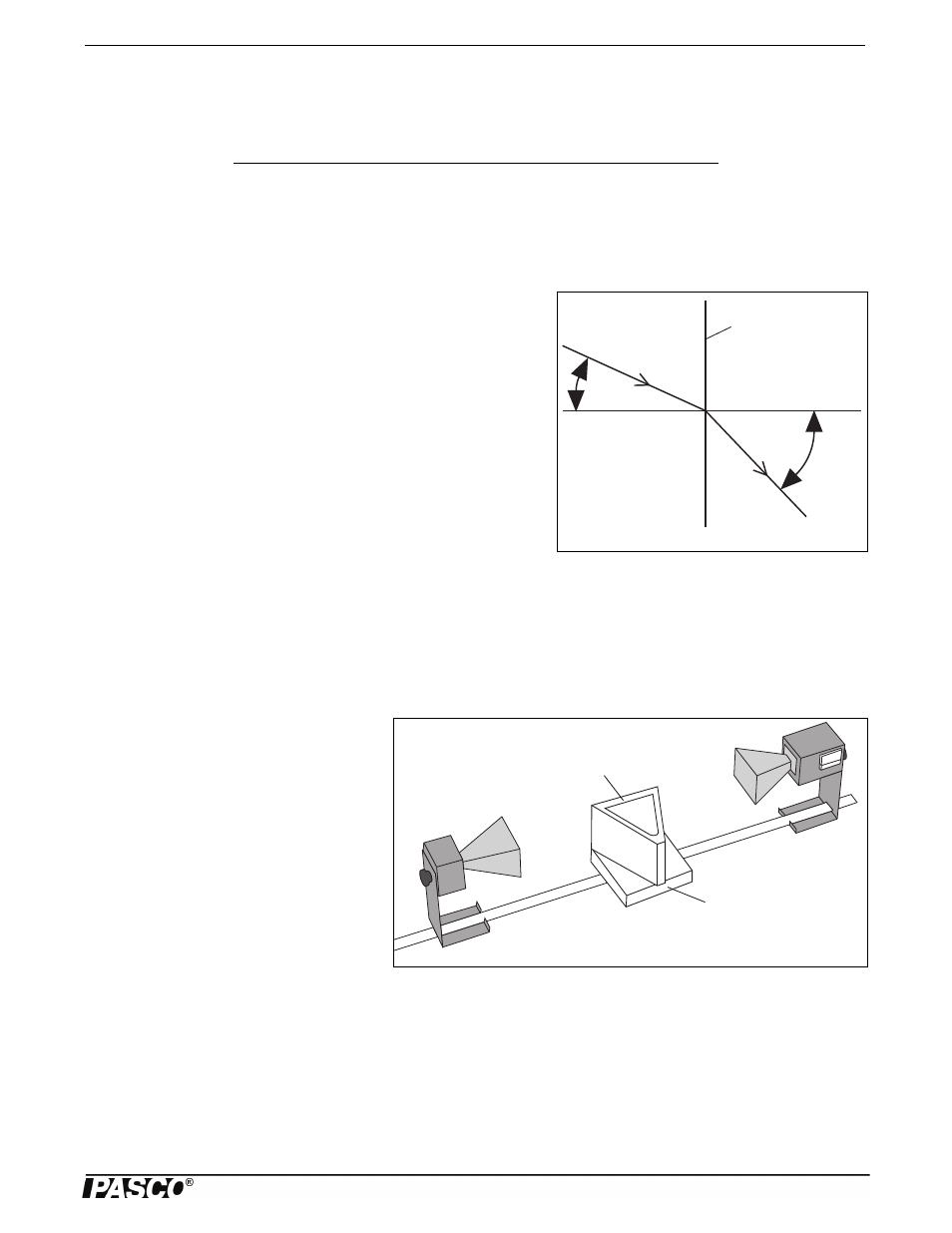
An electromagnetic wave usually travels in a straight line. As it crosses a
boundary between two different media, however, the direction of propaga-
tion of the wave changes. This change in direction is called Refraction, and
it is summarized by a mathematical relationship known as the Law of
Refraction (otherwise known as Snell’s Law):
n
1
sin
1
= n
2
sin
2
;
where
1
is the angle between the direction of propagation of the incident
wave and the normal to the boundary between the two media, and
2
is the
corresponding angle for the refracted wave (see Figure 4.1). Every mate-
rial can be described by a number n, called its Index of Refraction. This
number indicates the ratio between the speed of electromagnetic waves in
vacuum and the speed of electromagnetic waves in the material, also called
the medium. In general, the media on either side of a boundary will have
different indices of refraction. Here they are labeled n
1
and n
2
. It is the dif-
ference between indices of refraction (and the difference between wave velocities that this implies) which causes “bending”, or
refraction of a wave as it crosses the boundary between two distinct media.
Purpose
In this experiment, you will use the law of refraction to measure the index of refraction for styrene pellets.
Procedure
1. Arrange the equipment as shown in Figure
4.2. Rotate the empty prism mold and see
how it effects the incident wave. Does it
reflect, refract, or absorb the wave?
2. Fill the prism mold with the styrene pellets.
To simplify the calculations, align the face
of the prism that is nearest to the Transmit-
ter so it is perpendicular to the incident
microwave beam.
3. Rotate the movable arm of the Goniometer
and locate the angle
at which the refracted
signal is a maximum.
NOTE:
is just the angle that you read directly from the Degree Scale of the Goniometer.
•
= _________________________.
Item
Item
Transmitter
Goniometer
Receiver
Rotating Table
Prism Mold with Styrene Pellets
Protractor
Figure 4.1: Angles of Incidence and Refraction
1
2
Boundary between
media
Incident Wave
Refracted
Wave
n
1
n
2
Figure 4.2: Equipment Setup
Prism Mold
Rotating Table