Experiment 7: lloyd’s mirror, Equipment needed, Introduction – PASCO WA-9316A Complete Microwave Optics System User Manual
Page 21: Purpose, Procedure, Equipment needed: introduction
013-13906B
Experiment 7: Lloyd’s Mirror
21
Experiment 7: Lloyd’s Mirror
Equipment Needed:
Introduction
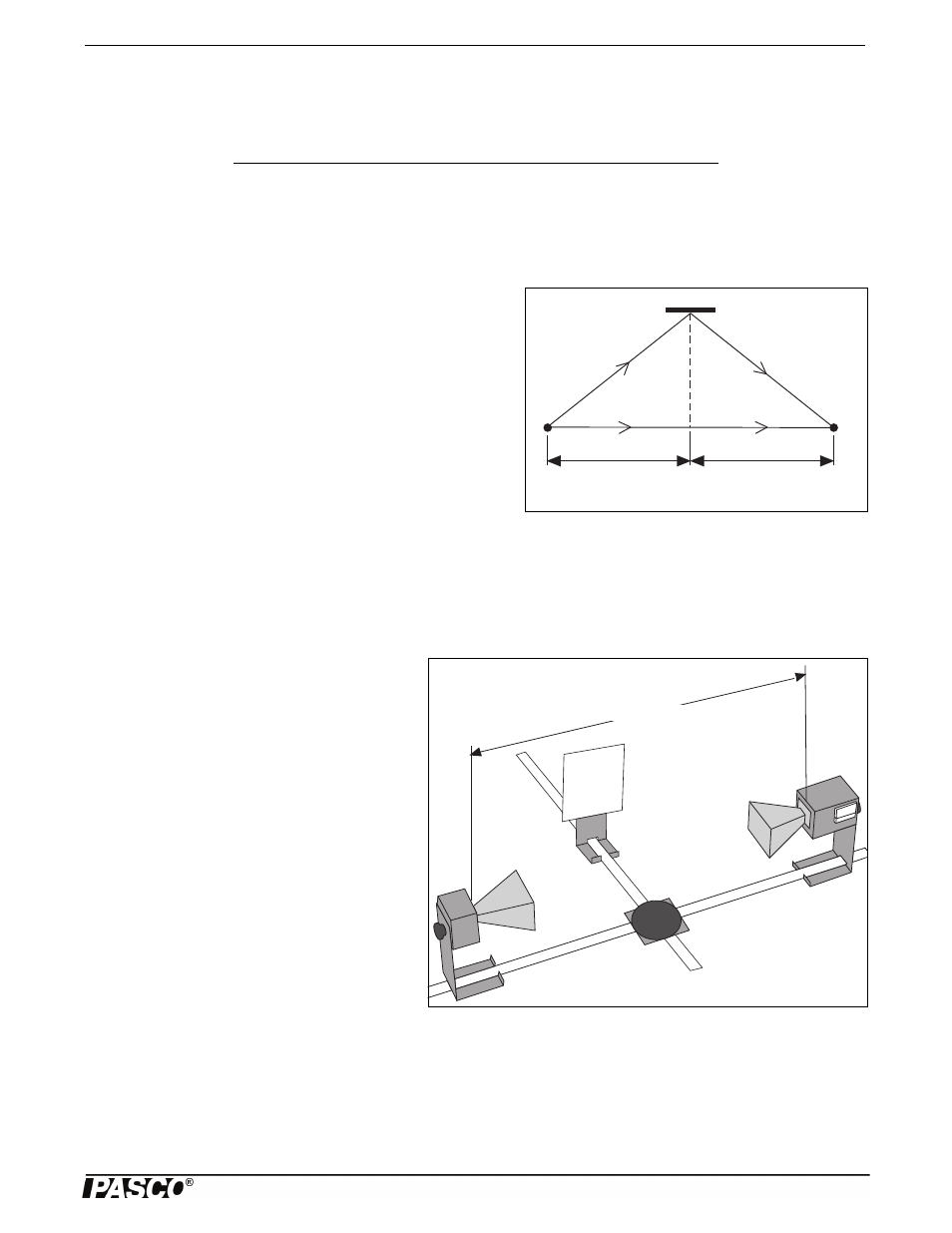
Figure 7.1: Lloyd’s Mirror
h
B
A
C
d
1
d
1
In earlier experiments, such as 3 and 6, you observed how a single
electromagnetic wave can be diffracted into two waves and, when the
two components join back together, they form an interference pattern.
Lloyd’s Mirror is another example of this phenomenon. Just as with
the other interference patterns you have seen, this interference pattern
provides a convenient method for measuring the wavelength of the
radiation.
Figure 7.1 is a diagram for Lloyd’s Mirror. An electromagnetic wave
from point source A is detected at point C. Some of the electromag-
netic wave, of course, propagates directly between point A and C, but
some reaches C after being reflected at point B. A maximum signal
will be detected when the two waves reach the detector in phase. Assuming that the diagram shows a setup for a maximum sig-
nal, another maximum will be found when the Reflector is moved back so the path length of the reflected beam is AB + BC +
. where is the wavelength of the electromagnetic wave,
Purpose
In this experiment you will investigate the phenomenon of an interference pattern formed by a Lloyd’s Mirror.
Procedure
Figure 7.2: Equipment Setup
1.0 meter or more
1. Arrange the equipment as shown in Figure 7.2.
For best results, the Transmitter and Receiver
should be as far apart as possible. Be sure the
Receiver and Transmitter are equidistant (d
1
)
from the center of the Goniometer degree plate
and that the horns are directly facing each other.
(See Figure 7.3 for location of effective points of
transmission and reception). Also be sure that the
surface of the Reflector is parallel to the axis of
the Transmitter and Receiver horns.
2. While watching the meter on the Receiver,
slowly slide the Reflector away from the Degree
Plate. Notice how the meter reading passes
through a series of minima and maxima.
3. Find the Reflector position closest to the degree
plate which produces a minimum meter reading.
4. Measure and record h
1
, the distance between the center of the degree plate and the surface of the Reflector.
•
h
1
= _________________________.
5. Slowly slide the Reflector away from the degree plate until the meter reading passes through a maximum and returns to a
new minimum. Measure and record h
2
, the new distance between the center of the degree plate and the surface of the
Reflector.
Item
Item
Transmitter
Goniometer
Receiver
Component Holder)
Fixed Arm Assembly
Reflector (1)
Meter Stick