Experiment 11: brewster’s angle, Equipment needed, Introduction – PASCO WA-9316A Complete Microwave Optics System User Manual
Page 29: Purpose, Procedure
013-13906B
Experiment 11: Brewster’s Angle
29
Experiment 11: Brewster’s Angle
Equipment Needed:
Introduction
When electromagnetic radiation passes from one media into another, some of the radiation usually reflects from the surface of
the new medium. In this experiment, you will find that the magnitude of the reflected signal depends on the polarization of the
radiation. In fact, at a certain angle of incidence—known as Brewster’s Angle—there is an angle of polarization for which no
radiation will be reflected. (Check your textbook for more information on Brewster’s Angle.).
Purpose
In this experiment you will investigate the Brewster’s Angle.
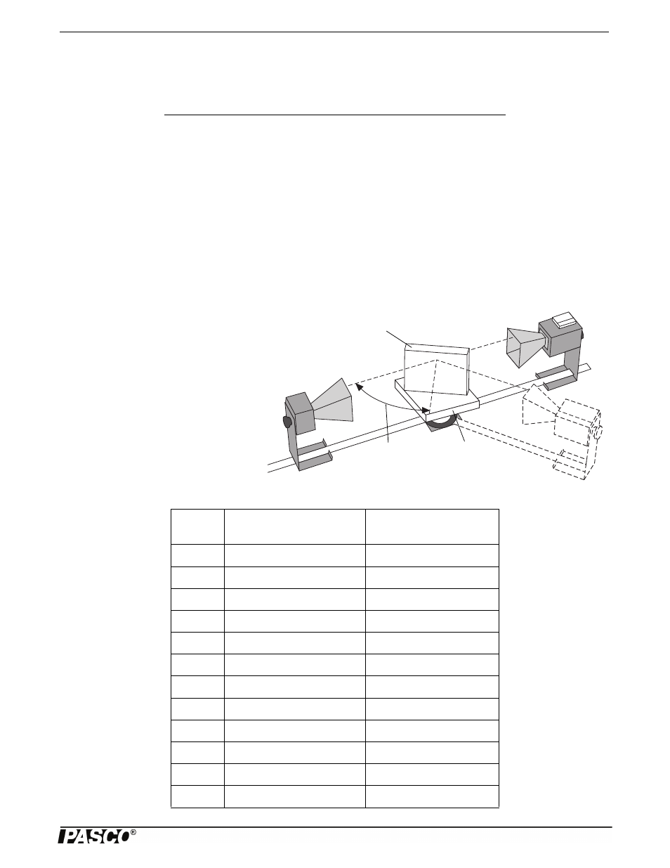
Procedure
Angle of
Incidence
Rotating
Table
Polyethylene
Panel
1. Arrange the equipment as shown in Fig-
ure 11.1, setting both the Transmitter and
the Receiver for horizontal polarization
(90°).
2. Adjust the Panel so the angle of incidence
of the microwave from the Transmitter is
20°. Rotate the Goniometer arm until the
Receiver is positioned where it can detect
the maximum signal reflected from the
Panel. Adjust the Receiver controls for a
mid-scale reading, and record the meter
reading in Table 11.1.
Item
Item
Transmitter
Goniometer
Receiver
Rotating Table
Polyethylene Panel
Angle
Meter Reading
(Horizontal Polarization)
Meter Reading
(Vertical Polarization)
20°
25°
30°
35°
40°
45°
50°
55°
60°
65°
70°
75°