Experiment 2: reflection – PASCO WA-9316A Complete Microwave Optics System User Manual
Page 34
013-13906B
Teacher’s Guide
34
Experiment 2: Reflection
Notes on the Procedure
5.
The last three points are suspect due to the spread of the output pattern of the transmitter. See Experiment 1, part 8.
Answers to Questions
1. The angle of incidence equals the angle of reflection. This does hold for all angles, although it is not clear in this experi-
ment due to the spread in the output pattern.
2. Some of the wave appeared to reflect into different angles; particularly when the angle of incidence was 70° or 90°. This
is actually a diffraction effect, not reflection.
3. The transmitter does not produce a perfect plane wave, and this does affect the results.
Answers to Questions for Additional Experimentation
1. Intensity of the reflection does vary with the angle of incidence; from this we can deduce that the reflector is not 100%
efficient.
2. In general, conductors will reflect the microwaves much better than non-conductors.
3.
Experiment 3: Standing Waves - Measuring Wavelengths
Notes on the Procedures
Method A
Average wavelength: 2.70 cm
Frequency: 1.11 x 10
10
Hz
(Fewer points were taken due to the limited resolution of this method.)
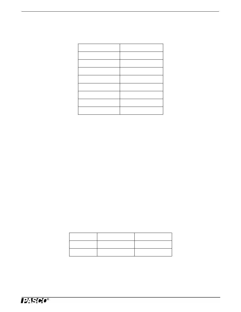
Table 2.1: Data
Angle of Incidence
Angle of Reflection
20°
23°
30°
31°
40°
41°
50°
52°
60°
63°
70°
85°
80°
78°
90°
70°
Antinodes
Distance (cm)
Wavelength (cm)
10
13.3
2.66
15
20.5
2.73