Experiment 5: polarization, Equipment needed, Introduction – PASCO WA-9316A Complete Microwave Optics System User Manual
Page 17: Purpose, Procedure
013-13906B
Experiment 5: Polarization
17
Experiment 5: Polarization
Equipment Needed:
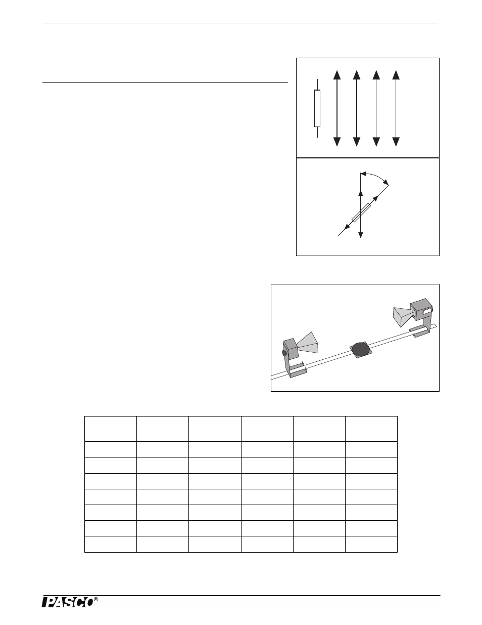
Figure 5.1: Vertical Polarization
Transmitter
Diode
Vertically
Polarized
Microwaves
(E field)
Introduction
Figure 5.2: Detecting Polarized Radiation
Detector
Diode
Component
Detected
Vertically
Polarized
Microwaves
The microwave radiation from the Transmitter is linearly polarized along the
Transmitter diode axis (i.e., as the radiation propagates through space, its elec-
tric field remains aligned with the axis of the diode). If the Transmitter diode
were aligned vertically, the electric field of the transmitted wave would be ver-
tically polarized, as shown in Figure 5.1. If the detector diode were at an angle
to the Transmitter diode, as shown in Figure 5.2, it would only detect the
component of the incident electric field that was aligned along its axis.
Purpose
In this experiment you will investigate the phenomenon of polarization and dis-
cover how a polarizer can be used to alter the polarization of microwave radiation.
Procedure
Figure 5.3: Equipment Setup
1. Arrange the equipment as shown in Figure 5.3 and adjust the
Receiver controls for nearly full-scale meter deflection.
2. Loosen the hand screw on the back of the Receiver and rotate the
Receiver in increments of ten degrees. At each rotational position,
record the meter reading in Table 5.1.
3. What happens to the meter readings if you continue to rotate the
Receiver beyond 180-degrees
Item
Item
Transmitter
Goniometer
Receiver
Polarizer (1)
Component Holder (2)
Table 5.1: Data
Angle of
Receiver
Meter
Reading
Angle of
Receiver
Meter
Reading
Angle of
Receiver
Meter
Reading
0°
70°
140°
10°
80°
150°
20°
90°
160°
30°
100°
170°
40°
110°
180°
50°
120°
60°
130°