PASCO WA-9316A Complete Microwave Optics System User Manual
Page 6
Experiment Guide
Experiment 1: Introduction to the Microwave Optics System
6
5. Set R to some value between 70 and 90 cm. While watching the meter, slowly decrease the distance between the Trans-
mitter and Receiver. Does the meter deflection increase steadily as the distance decreases?
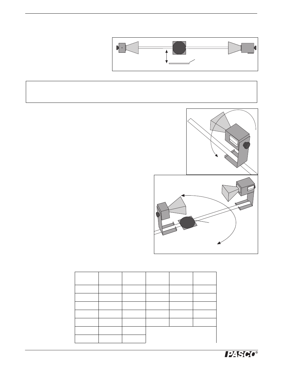
6. Set R to between 50 and 90 cm. Move a
Reflector, its plane parallel to the axis of
the microwave beam, toward and away
from the beam axis, as shown in Figure
1.3. Observe the meter readings. Can you
explain your observations in steps 5 and
6? (Don’t worry if you can’t; you will
have a chance to investigate these phenomena more closely in other experiments.) For now just be aware of the following:
7. Loosen the hand screw on the back of the Receiver and rotate the Receiver as
shown in Figure 1.4. This varies the polarity of maximum detection. (Look into
the receiver horn and notice the alignment of the detector diode.) Observe the
meter readings through a full 360 degree rotation of the horn. A small mirror may
be helpful to view the meter reading as the receiver is turned. At what polarity
does the Receiver detect no signal?
NOTE: Try rotating the Transmitter horn as well. When finished, reset the Transmitter
and Receiver so their polarities match (e.g., both horns are horizontal or both horns
are vertical).
8. Position the Transmitter so the output surface of the horn is cen-
tered directly over the center of the Degree Plate of the Goni-
ometer arm (see Figure 1.5). With the Receiver directly facing
the Transmitter and as far back on the Goniometer arm as possi-
ble, adjust the Receiver controls for a meter reading of 1.0.
Then rotate the rotatable arm of the Goniometer as shown in the
figure. Set the angle of rotation (measured relative to the
180-degree point on the degree scale) to each of the values
shown in Table 2, and record the meter reading at each setting
.
Table 1.2: Data
Angle of
Receiver
Meter
Reading
Angle of
Receiver
Meter
Reading
Angle of
Receiver
Meter
Reading
90°
160
230
100
170
240
110
180
250
120
190
260
130
200
270
140
210
150
220
Reflector
Figure1.3: Reflections
IMPORTANT: Reflections from nearby objects, including the table top, can affect the results of your microwave exper-
iments. To reduce the effects of extraneous reflections, keep your experiment table clear of all objects, especially metal
objects, other than those components required for the current experiment.
Figure1.4: Polarization
Figure1.5: Signal Distribution
Angle = 180°