Experiment 6: double-slit interference, Equipment needed, Introduction – PASCO WA-9316A Complete Microwave Optics System User Manual
Page 19: Purpose, Procedure
013-13906B
Experiment 6: Double-Slit Interference
19
Experiment 6: Double-Slit Interference
Equipment Needed:
Introduction
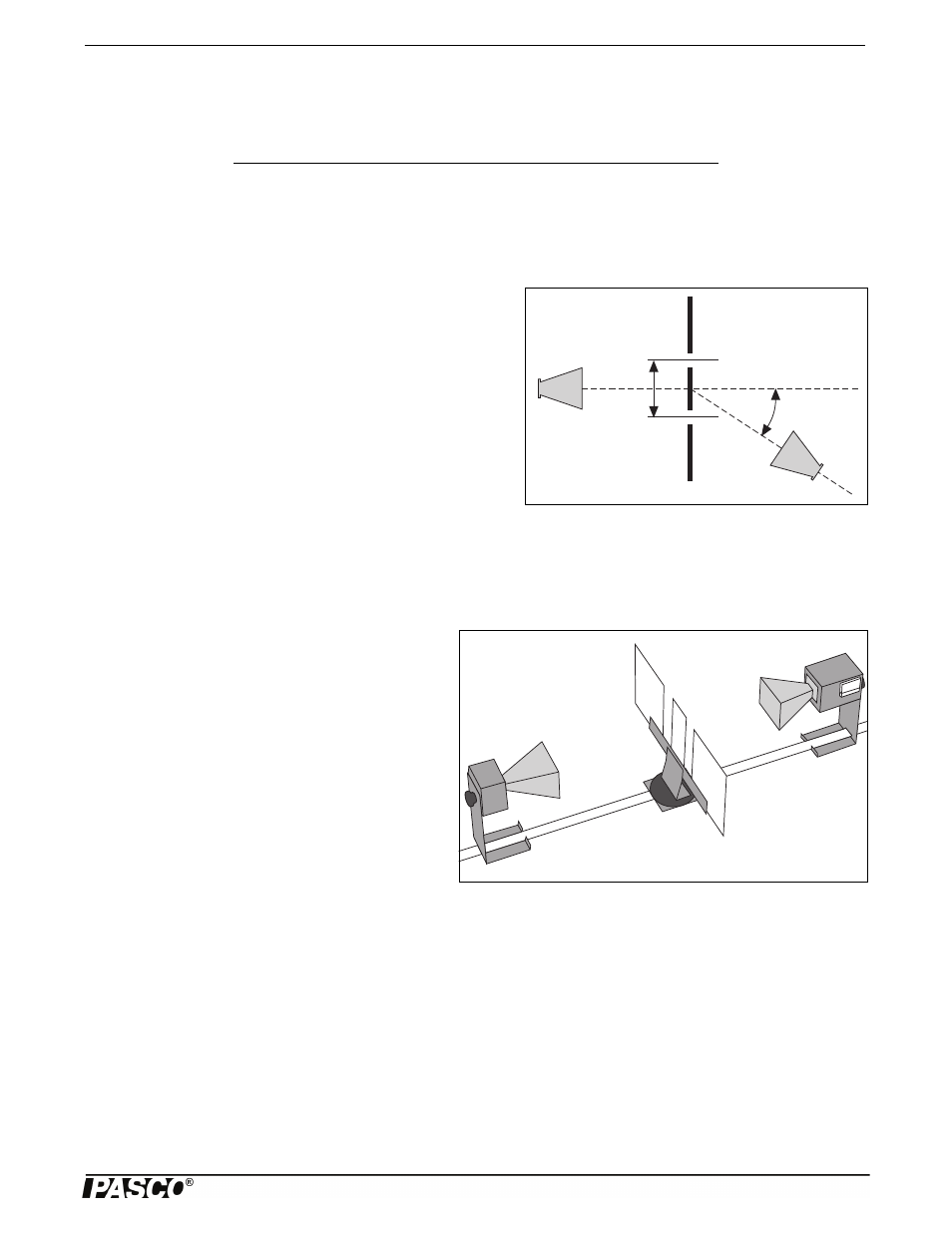
Figure 6.1: Double-Slit Interference
d
Experiment 3 showed that two waves moving in opposite directions
can superpose to create a standing wave pattern. A somewhat similar
phenomenon occurs when an electromagnetic wave passes through a
two-slit aperture. The wave diffracts into two waves which superpose
in the space beyond the apertures. Similar to the standing wave pat-
tern, there are points in space where maxima are formed and others
where minima are formed.
With a double slit aperture, the intensity of the wave beyond the aper-
ture will vary depending on the angle of detection. For two thin slits
separated by a distance d, maxima will be found at angles such that
d sin
= n. (where = the angle of detection, = the wavelength of the incident radiation, and n is any integer; see Figure
6.1). Refer to a textbook for more information about the nature of the double-slit diffraction pattern.
Purpose
In this experiment you will investigate the phenomena of diffraction and interference.
Procedure
Figure 6.2: Equipment Setup
1. Arrange the equipment as shown in Figure 6.2. Use
the Slit Extender Arm, two Reflectors, and the Narrow
Slit Spacer to construct the double slit. (A slit width of
about 1.5 cm is recommended.) Be precise with the
alignment of the slit and make the setup as symmetri-
cal as possible.
2. Adjust the Transmitter and Receiver for vertical polar-
ization (0°) and adjust the Receiver controls to give a
full-scale reading at the lowest possible amplification.
3. Rotate the rotatable Goniometer arm (on which the
Receiver rests) slowly about its axis. Observe the
meter readings.
4. Reset the Goniometer arm so the Receiver directly faces the Transmitter. Adjust the Receiver controls to obtain a meter
reading of 1.0. Now set the angle
to each of the values shown in Table 6.1. At each setting record the meter reading in
the table. (In places where the meter reading changes significantly between angle settings, you may find it useful to inves-
tigate the signal level at intermediate angles.)
5. Keep the slit widths the same, but change the distance between the slits by using the Wide Slit Spacer instead of the Nar-
row Slit Spacer. Because the Wide Slit Space is 50% wider than the Narrow Slit Spacer (9 cm vs 6 cm) move the Trans-
Item
Item
Transmitter
Goniometer
Receiver
Rotating Component Holder)
Slit Extender Arm
Metal Reflectors (2)
Wide Slit Spacer
Narrow Slit Spacer