Experiment 8: fabry-perot interferometer, Equipment needed, Introduction – PASCO WA-9316A Complete Microwave Optics System User Manual
Page 23: Procedure, Equipment needed: introduction
013-13906B
Experiment 8: Fabry-Perot Interferometer
23
Experiment 8: Fabry-Perot Interferometer
Equipment Needed:
Introduction
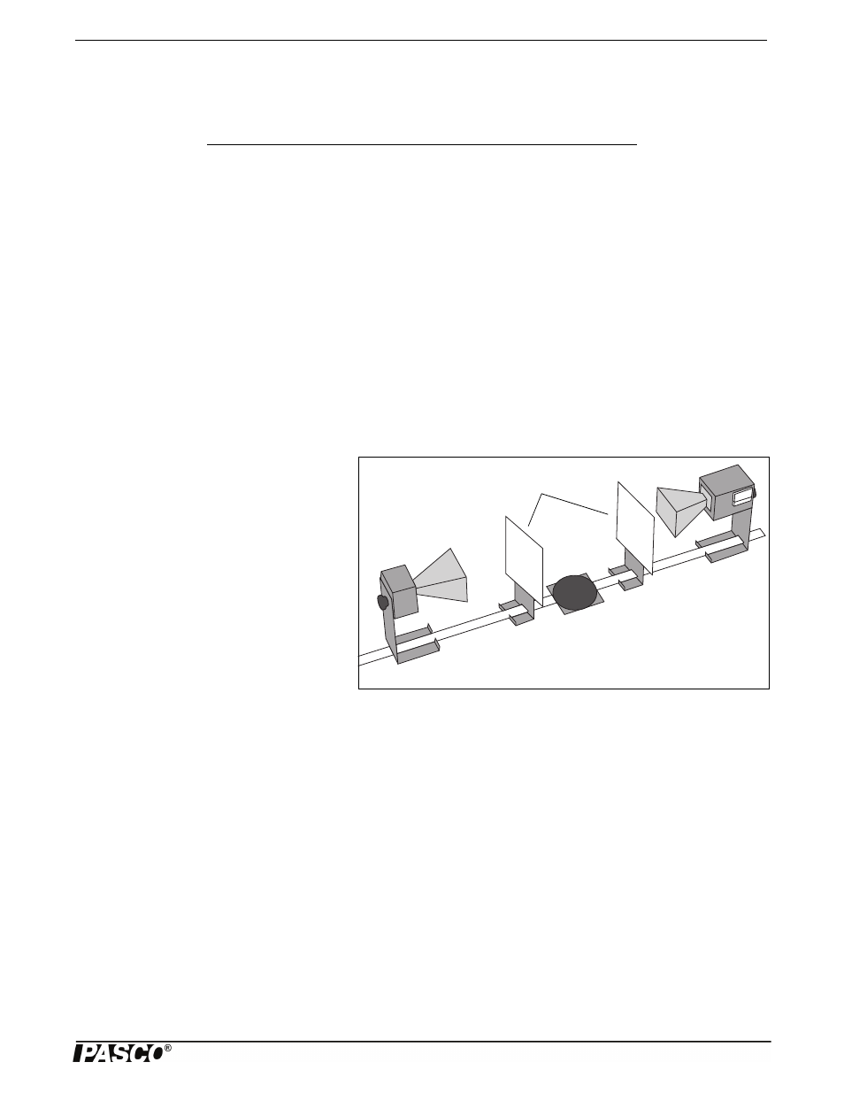
When an electromagnetic wave encounters a partial reflector, part of the wave reflects and part of the wave transmits through
the partial reflector. A Fabry-Perot Interferometer consists of two parallel partial reflectors positioned between a wave source
and a detector (see Figure 8.1).
The wave from the source reflects back and forth between the two partial reflectors. However, with each pass, some of the
radiation passes through to the detector. If the distance between the partial reflectors is equal to n
/2, where is the wave-
length of the radiation and n is an integer, then all the waves passing through to the detector at any instant will be in phase. In
this case, a maximum signal will be detected by the Receiver. If the distance between the partial reflectors is not a multiple of
2, then some degree of destructive interference will occur, and the signal will not be a maximum.
Purpose
In this experiment you will investigate the Fabry-Perot Interferometer.
Procedure
Figure 8.1: Equipment Setup
Partial Reflectors
1. Arrange the equipment as shown in Figure
8.1. Plug in the equipment and adjust the
Receiver controls for an easily readable sig-
nal.
2. Adjust the distance between the Partial
Reflectors and observe the relative minima
and maxima.
3. Adjust the distance between the Partial
Reflectors to obtain a maximum meter read-
ing. Record, d
1
, the distance between the
reflectors.
•
d
1
= _________________________.
4. While watching the meter, slowly move one Reflector away from the other. Move the Reflector until the meter reading has
passed through at least 10 minima and returned to a maximum. Record the number of minima that were traversed. Also
record d
2
, the new distance between the Reflectors.
•
Minima traversed = _________________________.
•
d
2
= _________________________.
5. Use your data to calculate
, the wavelength of the microwave radiation.
•
= _________________________.
6. Repeat your measurements, beginning with a different distance between the Partial Reflectors.
•
d
1
= _________________________. Minima traversed = _________________________.
•
d
2
= _________________________.
= _________________________.
Item
Item
Transmitter
Goniometer
Receiver
Component Holders (2)
Partial Reflectors (2)