Experiment 8: fabry-perot interferometer – PASCO WA-9316A Complete Microwave Optics System User Manual
Page 39
013-13906B
Teacher’s Guide
39
Experiment 8: Fabry-Perot Interferometer
Notes on the Procedure
1. through 4.
For best results, do not move the reflector closest to the transmitter. There are actually two standing wave patterns that may
form: one between the transmitter and first reflector, and one between the two reflectors. (There may also be others, such as
between the second reflector and the receiver or the second reflector and the transmitter; but these will be negligible.) Moving
the first reflector will change the amplitude of the wave coming into the region between the reflectors, and thus give erroneous
results.
First plate: 75.2 mm
5. and 6.
2.85 cm
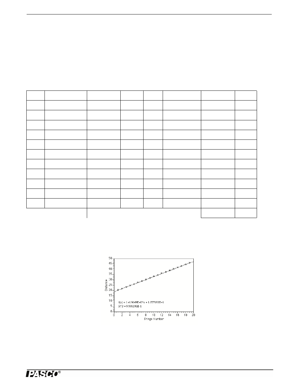
NOTE: An alternate method of analysis is to make a graph of distance versus fringe number and take the slope of the line to
find the wavelength.
Answers to Questions
1. Minima will occur when the spacing is n
4, where n is an odd integer.
2. Normally, just such a pattern would occur; in this case, however, the reflectors are too small in relation to the wavelength
used; so the next “ring” is located beyond the edge of the reflectors and may not be seen.
n
Second plate
Distance
D
n
Second plate
Distance
D
1
54.9
20.3
12
39.4
35.8
1.4
2
53.6
21.6
1.3
13
38.0
37.2
1.4
3
52.2
23.0
1.4
14
36.6
38.6
1.4
4
50.9
24.3
1.3
15
35.1
40.1
1.5
5
49.4
25.8
1.5
16
33.8
41.4
1.3
6
47.9
27.3
1.5
17
32.3
42.9
1.5
7
46.5
28.7
1.4
18
30.9
44.3
1.4
8
45.0
30.2
1.5
19
29.4
45.8
1.5
9
43.6
31.6
1.4
20
27.9
47.3
1.5
10
42.1
33.1
1.5
21
26.5
48.7
1.4
11
40.8
34.4
1.3
22
25.0
50.2
1.5
Average
1.42