Equipment needed, Introduction, Purpose – PASCO WA-9316A Complete Microwave Optics System User Manual
Page 11: Procedure
013-13906B
Experiment 3: Standing Waves – Measuring Wavelength
11
Experiment 3: Standing Waves – Measuring Wavelength
Equipment Needed:
Introduction
When two electromagnetic waves meet in space, they superpose. The superposition principle describes that the total electric
field at any point is the sum of the electric fields created by both waves at that point. If the two waves travel at the same fre-
quency but in opposite direction, they form a standing wave. Nodes appear where the fields of the two waves cancel and
antinodes appear where the superposed fields oscillate between a maximum and a minimum. The distance between nodes in
the standing wave pattern is just one-half (1/2) the wavelength,
of the two waves.
Purpose
In this experiment, you will reflect the wave from the Transmitter back upon itself, creating a standing wave pattern. By mea-
suring the distance between nodes in the pattern and multiplying by two, you can determine the wavelength,
, of the micro-
wave radiation.
Procedure
Method A
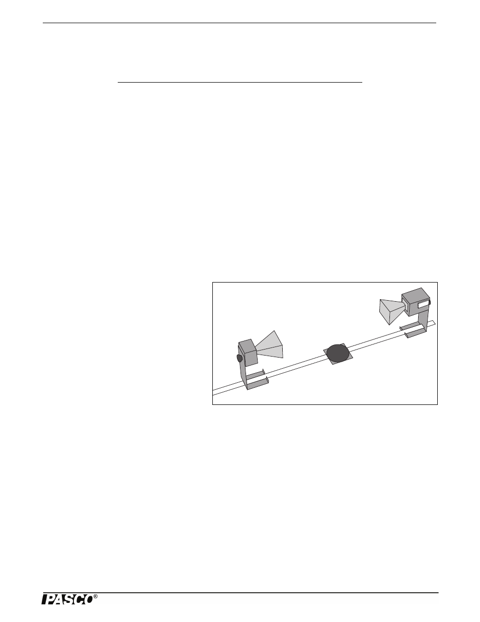
1. Set up the equipment as shown in Figure 3.1.
Adjust the Receiver controls to get a full-scale
meter reading with the Transmitter and Receiver
as close together as possible. Slowly move the
Receiver along the Goniometer arm away from
the Transmitter. How does this motion effect the
meter reading?
NOTE: The microwave horns are not perfect collec-
tors of microwave radiation. Instead, they act as par-
tial reflectors, so that the radiation from the
Transmitter reflects back and forth between the
Transmitter and Reflector horns, diminishing in
amplitude at each pass. However, if the distance
between the Transmitter and Receiver diodes is equal to n
/2, (where n is an integer and is the wavelength of the radiation),
then all the multiply-reflected waves entering the Receiver horn will be in phase with the primary transmitted wave. When this
occurs, the meter reading will be a maximum. (The distance between adjacent positions in order to see a maximum is therefore
/2.)
2. Slide the Receiver one or two centimeters along the Goniometer arm to obtain a maximum meter reading. Record the
Receiver position along the metric scale of the Goniometer arm.
•
Initial Position of Receiver = _________________________.
3. While watching the meter, slide the Receiver away from the Transmitter. Do not stop until the Receiver passed through at
least 10 positions at which you see a minimum meter reading and it returned to a position where the reading is a maxi-
mum. Record the new position of the Receiver and the number of minima that were traversed.
•
Minima Traversed= _________________________.
•
Final Receiver Position = _________________________.
4. Use the data you have collected to calculate the wavelength of the microwave radiation.
Item
Item
Transmitter
Goniometer
Receiver
Reflector
Component Holder (2)
Optional: Microwave Detector Probe
Figure 3.1: Equipment Setup