Setting up the equipment – PASCO OS-8500 INTRODUCTORY OPTICS SYSTEM User Manual
Page 9
012-02744K
Introductory Optics System
®
3
Setting Up the Equipment
The Filament Knob on the top of the unit moves the light
bulb from side to side. The notch at the bottom indicates
the position of the light bulb filament, so that accurate
measurements can be made during experiments.
Component
Holders and
Components
The Optics set comes
with three regular
Component Holders
and one holder
designed for use with
the Ray Table. The
regular Component
Holders attach
magnetically to the
optics bench, as in
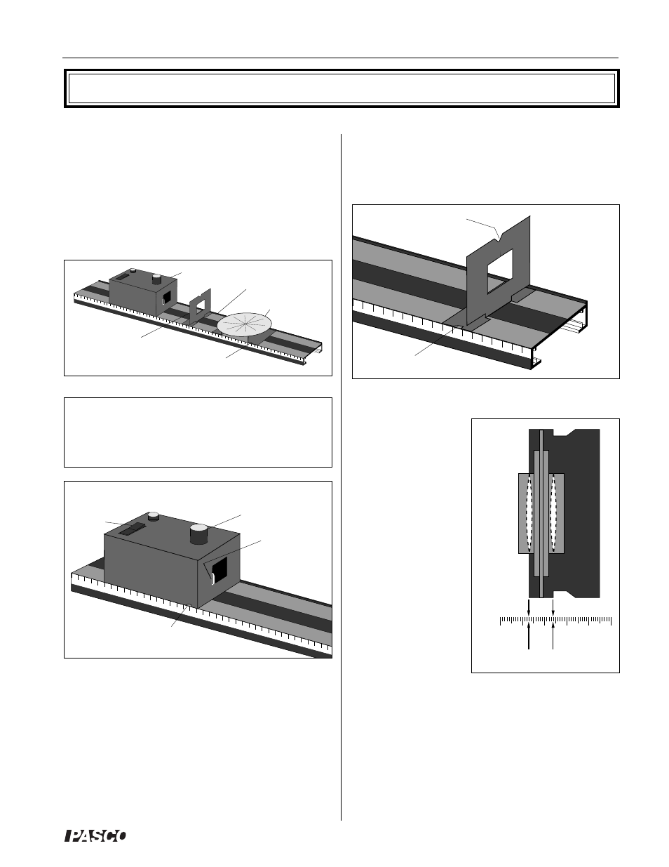
Figure 4. The notch at
the top of each holder
is for centering
components on the
holder. The notches in
the base of the holders
are for accurate
distance measurements on the metric scale of the bench.
These base notches—and also the edge of the component
holder base—are positioned so that they align with the
vertical axis of a mounted lens or mirror. Accurate
measurements of component position can be made as
shown in Figure 5.
Figure 2: Bench
Light Source
Ray Table Base
Component
Holder
Alignment Rail
Ray Table
Figure 5: Component
Alignment
(Top View)
0 1
2 3 4 5
Vertical Axes of Lens or Mirror
Centering
Notch
Figure 4: Using the Component Holders
Base Notch
Optics Bench
The Optics Bench is shown in Figure 2. The Light Source,
Component Holders, and Ray Table Base all attach magneti-
cally to the bench as shown. For proper optical alignment, the
edge of each of these components should be mounted flush to
the alignment rail, which is the raised edge that runs along one
side of the bench.
NOTE: Avoid scratching or otherwise abusing the surface
of the magnetic pads. If they get dirty, use only soapy
water or rubbing alcohol for cleaning. Other solvents may
dissolve the magnetic surface.
Incandescent Light Source
The Light Source is shown in Figure 3. To turn it on,
connect the power cord to any grounded 105-125 VAC
receptacle, and flip the switch on the top panel to ON. If
at any time the light fails to come on, check with your
instructor.
Filament Knob
Notch Showing Location of
Filament
ON
Switch
Light Bulb
Figure 3: Using the Light Source