PASCO OS-8500 INTRODUCTORY OPTICS SYSTEM User Manual
Page 38
Introductory Optics System
012-02744K
®
32
Why is one focal length shorter than the other? (Hint: consider the refraction of the light rays at both
surfaces of the lens.)____________________________________________________.
Image Location
Remove the Slit Mask from the front of the Light Source. Move the Ray Table and Base so it is as far
from the Light Source as possible. Set the Cylindrical Lens on the Ray Table with the straight side toward
the Light Source.
➀ Where is the image formed? ___________________________________________________.
➁ What happens to the location of the image as you move the Light Source closer?
_____________________________________________________________________.
➂ Is an image still formed when the Light Source is closer than the focal length of the lens? If so, what
kind? ______________________________________________________________.
Magnification and Inversion
In the plane of the Ray Table, the filament of the Light Source acts as a point source. To observe magni-
fication and inversion, an extended source is needed. As shown below, two positions of the Light
Source filament can be used to define an imaginary arrow, of height h
o
.
Position the filament of the Light Source first at the tail of the imaginary arrow, then at the tip. At each
position, locate the image of the filament. The height of the image arrow, h
i
, divided by the height of the
object arrow, h
o
, is the magnification of the image.
Measure the magnification for several different distances between the Light Source and the lens.
➀ Qualitatively, how does the degree of magnification depend on the distance between the object and the
lens?________________________________________________________________.
➁ Is the image inverted? Is it inverted for all object loca-
tions?______________________________________________________________________.
Cylindrical Aberration
Cylindrical aberration is the distortion of the image caused by imperfect focusing of the refracted rays.
Place a blank sheet of paper over the Ray Table. Arrange the equipment as in Figure 13.1 so all the light
rays are refracted by the Cylindrical Lens. Use the Slit Mask to block all but two rays. Do this for several
pairs of rays.
➀ Are all the rays focused at precisely the same point? ________________________________.
➁ How would you alter the shape of the lens to reduce the amount of cylindrical aberration?
_____________________________________________________________________________.
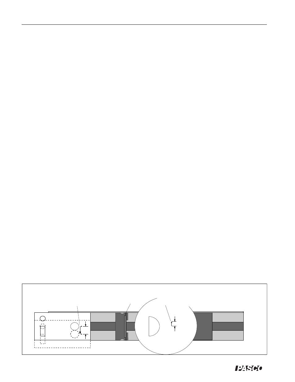
Figure 13.2 Magnification and Inversion
h
o
h
i
Slit Plate
Two positions of the light
source filament define an
imaginary arrow.
For each position of the filament,
an image is formed, defining the
image of the imaginary arrow.