PASCO OS-8500 INTRODUCTORY OPTICS SYSTEM User Manual
Page 25
012-02744K
Introductory Optics System
®
19
Introduction
Given a lens of any shape and index of refraction, you could determine the shape and location of
the images it forms based only on the Law of Refraction. You need only apply the law along with
some of the ray tracing techniques you have already used. However, for spherical lenses (and for
spherical mirrors as well), there is a more general equation that can be used to determine the
location and magnification of an image. This equation is called the Fundamental Lens equation:
1/d
o
+ 1/d
i
= 1/f
where f is the focal length of the lens, and d
o
and d
i
are the distance from the mirror to the image
and object respectively (see Figure 7.1). The magnification of the image is given by the equation:
m = -d
i
/d
o
In this experiment, you will have an opportunity to test and apply these equations.
➤
➤
➤
➤
➤NOTE: Instead of the above equation, you may have learned the Fundamental Lens Equation
as S
o
S
i
= f
2
, where S
o
and S
i
are the distances between the principle focus of the lens and the
object and image, respectively. If so, notice that S
o
= d
o
- f, and S
i
= d
i
- f (see Figure 7.1).
Using these equalities, convince yourself that 1/d
o
+ 1/d
i
= 1/f and S
o
S
i
= f
2
are different
expressions of the same relationship.
Procedure
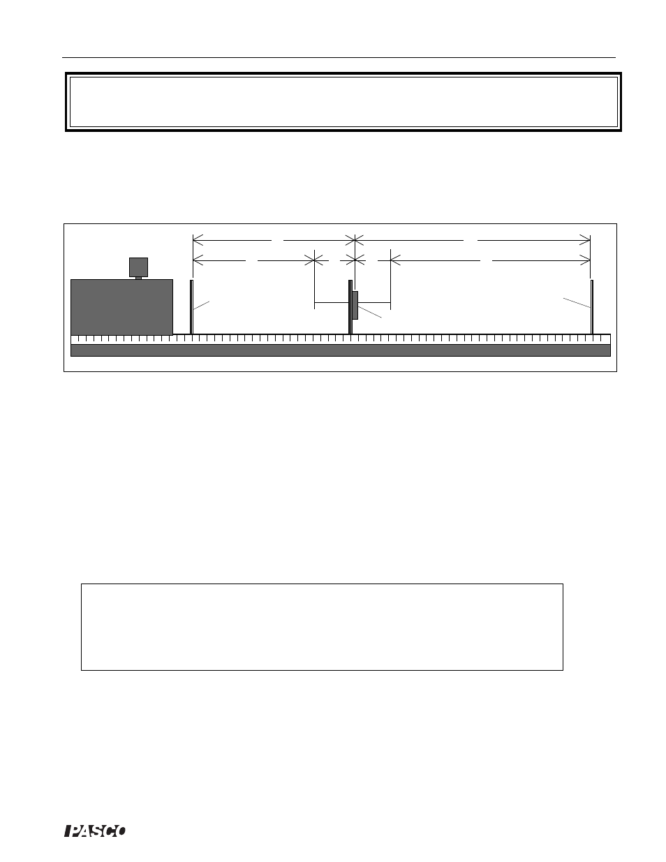
Set up the equipment as shown in Figure 7.1. Turn on the Light Source and slide the lens toward
or away from the Crossed Arrow Target, as needed to focus the image of the Target onto the
Viewing Screen.
➀ Is the image magnified or reduced? ____________________________________________.
➁ Is the image inverted?______________________________________________________.
➂ Based on the Fundamental Lens Equation, what would happen to d
i
if you increased d
o
even
further?_________________________________________________________________.
EQUIPMENT NEEDED:
-Optics Bench
-Light Source
-75 mm Focal Length Convex Lens
-Crossed Arrow Target
-Component Holders (3)
-Viewing Screen.
Experiment 7: Converging Lens – Image and Object
Relationships
Figure 7.1: Equipment Setup
Crossed Arrow
Target
Viewing Screen
Lens
d
i
d
o
S
o
S
i
f
f