Push buttons (sw1-4), Table 2-6. push button connections, Board reset push button (sw5) – Analog Devices EZ-KIT Lite ADSP-21364 User Manual
Page 49: Push buttons (sw1–4) -15, Board reset push button (sw5) -15, Push buttons (sw1–4)
ADSP-21364 EZ-KIT Lite Evaluation System Manual
2-15
ADSP-21364 EZ-KIT Lite Hardware Reference
Push Buttons (SW1–4)
Four push buttons (
SW1–4
) are provided for general-purpose user input.
Two push buttons connect to the
FLAG
pins of the processor. The other
two connect to the DAI of the processor. The push buttons are active high
and, when pressed, send a high (
1
) to the processor. Refer to
for more information. The push button
enable switch (
SW9
) is capable of disconnecting the push buttons from the
corresponding processor pins (refer to
for more information).
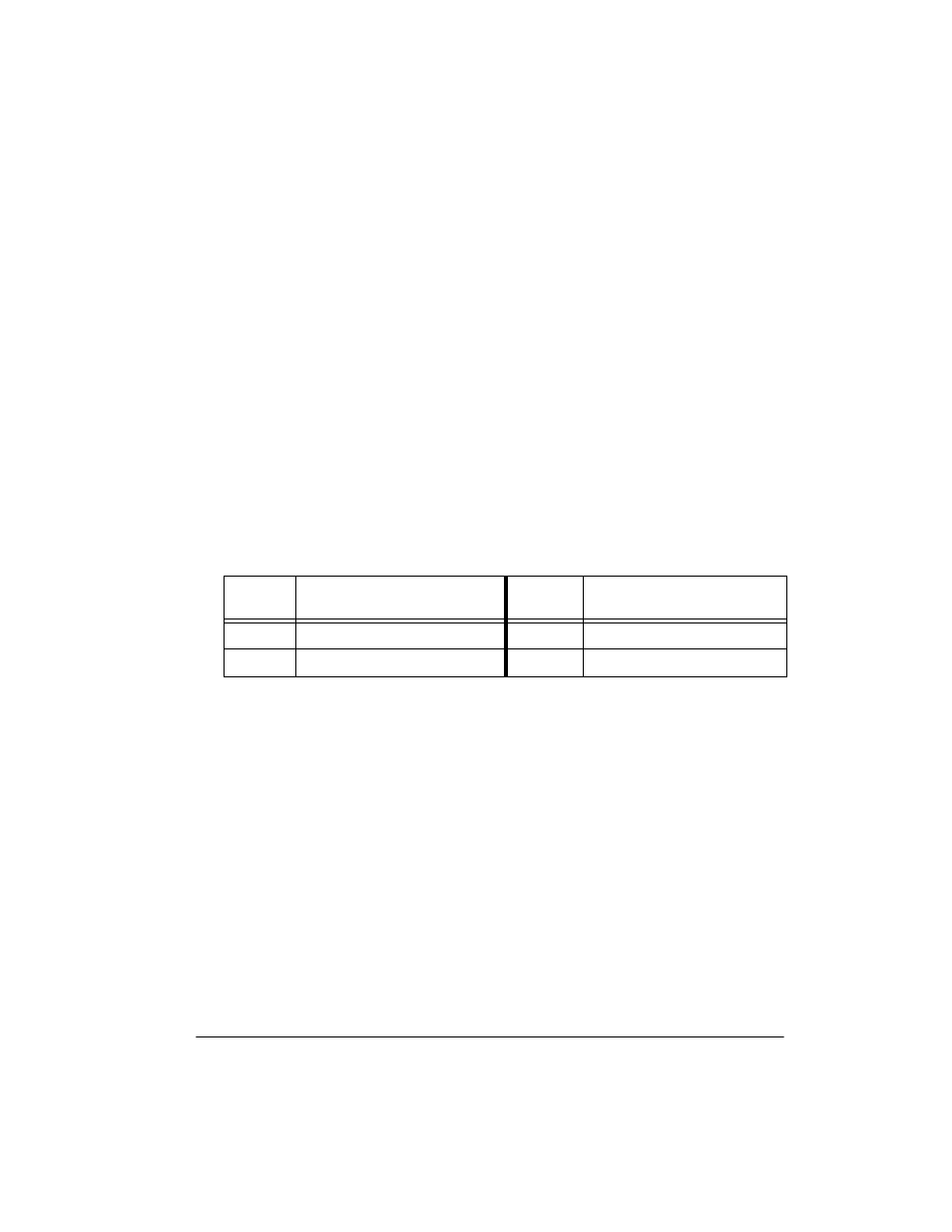
The processor signals and corresponding push buttons are summarized in
.
Board Reset Push Button (SW5)
The
RESET
push button (
SW5
) resets all of the ICs on the board.
Table 2-6. Push Button Connections
Processor
Signal
Push Button Reference
Designator
Processor
Signal
Push Button Reference
Designator
FLAG1
SW1
DAI_P19
SW3
FLAG2
SW2
DAI_P20
SW4