Leds and push buttons, Table 1-2. push button connections, Leds and push buttons -10 – Analog Devices EZ-KIT Lite ADSP-21364 User Manual
Page 32
LEDs and Push Buttons
1-10
ADSP-21364 EZ-KIT Lite Evaluation System Manual
LEDs and Push Buttons
The EZ-KIT Lite has eight general-purpose user LEDs and four gen-
eral-purpose push buttons.
Two of the general-purpose push buttons are attached to the
FLAG
pins of
the processor, while the other two are attached to the DAI pins. All of the
push buttons connect to the processor through a DIP switch. The DIP
switch can disconnect processor pins attached to the push buttons. See
“Push Button Enable Switch (SW9)” on page 2-11
for instructions on
how to disable the push buttons from driving the corresponding processor
pins.
The value of the push buttons connected to the
FLAG
pins can be deter-
mined by reading the
FLAG
register. The push buttons connected to the
DAI pins must be configured as interrupts. It is necessary to set up an
interrupt routine to determine each pin’s state.
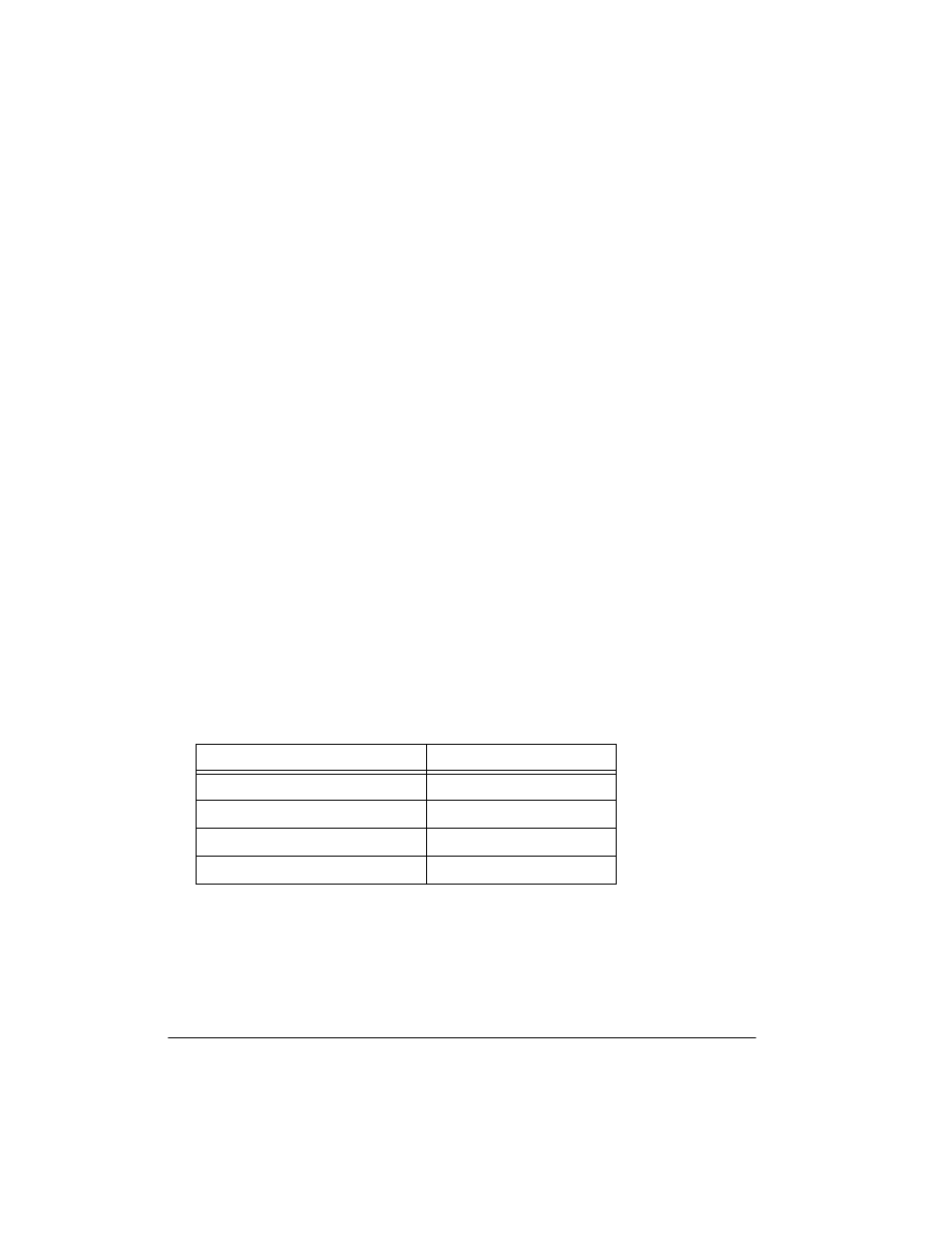
shows how each push button connects to the processor. Refer to
the related example program shipped with the EZ-KIT Lite for more
information.
Table 1-2. Push Button Connections
Push Button Reference Designator
Processor Pin
SW1
FLAG1
SW2
FLAG2
SW3
DAI_P19
SW4
DAI_P20