Accessory wiring – Controlled Products Systems Group PATRSL User Manual
Page 33
31
Accessory Wiring
Before wiring accessories to the Patriot control board remove the actuator connector plug from the control
board, this will disconnect power from the unit while wiring. Refer to the installation instructions provided with
the accessory being installed.
Typically the accessory will have 4 wires that we need to be concerned with (this can vary depending on the
manufacturer). These 4 wires can be divided into 2 groups.
First group consisting of 2 wires are the power wires – voltage connection and ground
Second group consisting of 2 wires are the control wires- N/O connection and common ground or ground
The power connection on the Patriot control board should be made at J2 pin 1. This output is protected with an
auto resetting 1.5-amp fuse. If the total current draw of all accessories exceeds 1.5 amps then it will be
necessary to connect directly to the battery for additional current.
The common, common ground or ground connection on the Patriot control board are located on the J2
connector (green) pin number 2 and 7, in addition the J1pin 2 and J4 pin 2 terminals located beside the J2
connector each have a ground connection. These are clearly marked on the control board. The battery ground or
– post can also be used if needed.
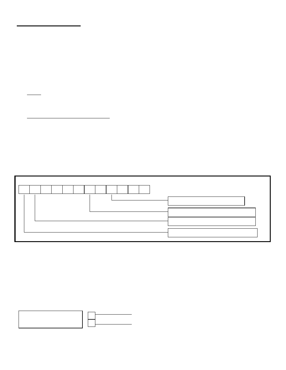
The N/O connection on the accessory will be made to the J2 connector (green) pin, which performs the desired
function. For example (Illustration 17) if installing a device with the desired function of opening the gate when
the accessory is activated then it connects to J2 pin 9. If the desired function is to reverse a gate that is closing
when activated then J2 pin 11. Refer to page 15 of this manual to understand J2 inputs and correct pin
connections.
The Patriot control board has 3 outputs that can be used to perform multiple functions they are the “Security
Shunt”, “Solenoid lock” and the “Magnetic lock” outputs. For any of these to operate the appropriate DS2
dipswitch must be turned on. See page 17 for DS2 location and functions.
Security Shunt – is a dry contact switch that is closed anytime the gate is not closed. A proximity switch such
as the type installed in a security system to activate an alarm if the contact is broken could be wired here. If the
gate is opened by an intended signal the security shunt switch closes and prevents the alarm system from
activating. If the gate were forced open then the alarm would be activated. Security shunt can also be used to
power +12-volt dc equipment. If the desired function is to have something turned on when the gate is not closed
for example a gate open indicator light. The security shunt would be wired as below.
The light’s ground connection can be made directly to the battery negative post. Light will come on when the
gate is not closed. This can also be used to power a Photo Eye in solar applications to reduce battery drain.
J2 connector (green)
1
2
11
3
4
5
9
6
7
8
10
12
To Accessory N.O connection
To Accessory Common or Ground
To Accessory Ground
To Accessory Power
Illustration 17
+12vdc power (Battery Positive Post)
To light positive connection
Security shunt terminal
on Patriot control board