Step 4 installation of charging source, Solar panel, Ac charger – Controlled Products Systems Group PATRSL User Manual
Page 13: Red wire + black wire, Panel facing southwest
11
STEP 4 Installation of Charging Source
SOLAR PANEL
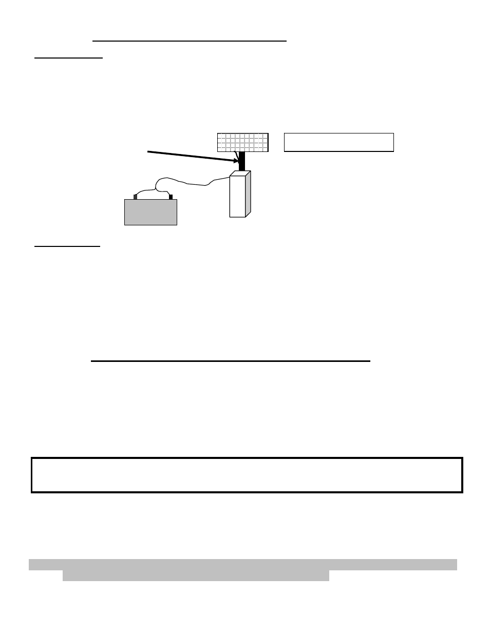
Locate and mount the solar panel bracket so that the panel faces southwest and maintains the preformed 45-
degree angle. The standard cable is 10' in length and must feed in through the bottom of the control box.
Pay attention to the distance when determining your mounting location. Although the cable can be extended
with watertight connectors, charging power is diminished. Sometimes it is necessary to locate the panel
farther away to achieve optimum sunlight, but consider that optimum sunlight might not mean optimum
charging if the distance is too great. Use #16 gauge wire or larger and keep length as short as possible.
Assemble panel(s) to bracket
with supplied hardware.
AC CHARGER
Locate and install the AC battery charger inside the operator chassis. A hole has been pre-punched for
conduit in the base of the operator (Illustration 14 page 9). The charger requires a receptacle for 110-volt AC
supply; recommended location is above the pre-punched hole. A licensed electrician per local building codes
should install the receptacle.
Modifying the charger power cord will void the charger warranty.
Note: USAutomatic recommends an AC surge protector on all 110-volt AC
installations, especially in lightning prone areas.
STEP 5 Control Board Dipswitch Setting Verification
NOTE: This check must be performed before operating the gate for the first time. Failure to do so
may damage the gate operator.
Before operating the gate lets make sure the Patriot control board dipswitches are set correctly for your installation.
Locate the dipswitches on the Patriot Control board (see page 16).
Factory default dipswitch settings are 2 and 3 on, right hand installation operator installed on right side of drive viewed
from inside the property.
Identify your installation below and verify dipswitch settings:
Patriot I (Right hand installation)
Dipswitches 2, 3 should be in the on position.
Patriot I (Left hand installation)
Dipswitches 2, 3, 9 should be in the on position.
NOTE: Left Hand Installations Only: (Inside property operator on left side of drive)
Left hand installations do not require rewiring the harnesses. The Patriot control board
dipswitch 9 eliminates the need to do this. Failure to turn dipswitch 9 on will cause improper
gate operation. Verify your installation type and verify dipswitch settings.
NOTE: The only thing to remember is that when dipswitch 9 is on, the Limit LED’s below the actuator plug on
the control board will show open when closed and closed when open.
AGM or Gel
Battery
Red wire +
Black wire -
NOTE: Avoid shaded areas if possible.
Panels should face southwest
for optimum charging. See
explanation above for details.
Panel facing southwest