Step 1 pad mount installation – Controlled Products Systems Group PATRSL User Manual
Page 11
9
STEP 1
Pad Mount Installation
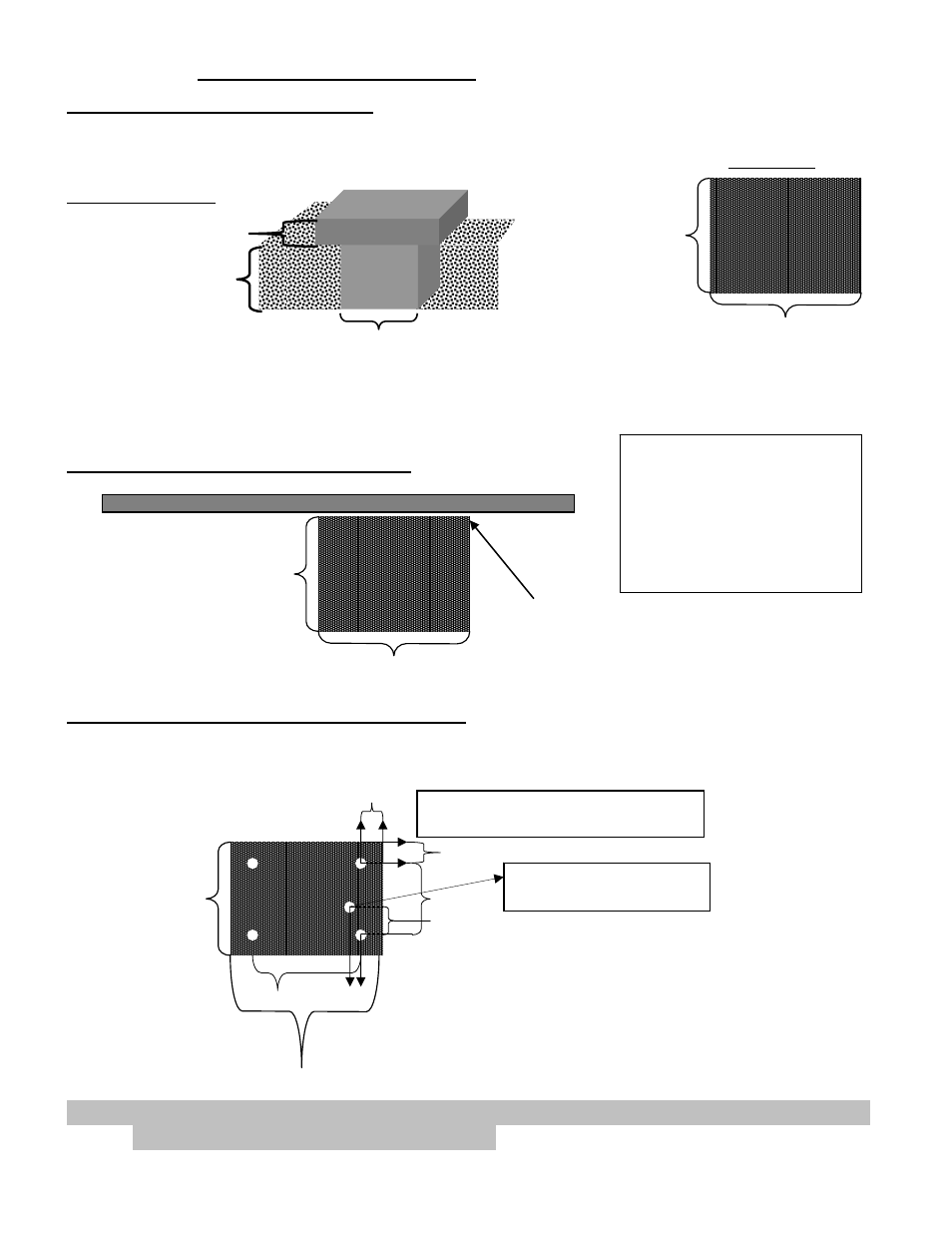
CONCRETE PAD CONSTRUCTION
The mounting foundation must be very stable and of sufficient strength to prevent any movement. Mounting
site must be clear of flooding.
Illustration shown is for dirt surface area. Surface areas of different material may require different pad
dimensions.
CONCRETE PAD LOCATION TO GATE
CONCRETE PAD ANCHOR BOLT LOCATION
Concrete pad top view measures 20” x 28”. This allows for 4” of concrete between the anchor bolts and the
outer edge of the pad. Use the drawing below to locate the four anchor bolts.
Note: USAutomatic is not responsible for failure to comply with UL-325 standards, local
building codes or improper installations.
TOP VIEW PAD
20” MINIMUM
28” MINIMUM
GATE TOP VIEW
20” MINIMUM
28” MINIMUM
Maximum Distance between
gate edge and pad edge 2.0”
Optimum 1.75”
20 inches
4 inches
4 inches
12 inches
Locate anchor boltholes on gate
side corners using these dimensions.
This hole is for ¾ electrical
conduit use dimensions shown.
TOP VIEW PAD
Gate Side
20” MINIMUM
28” MINIMUM
3.3 inches
1 inch
4-inch minimum
24-inch minimum
24-inch minimum
Cross Section View
Illustration 11
Illustration 12
Illustration 13
Illustration 14
When determining pad
location ensure that the
operator’s outer edge is a
safe distance away from the
driveway to avoid damage
from traffic.