Mounting operator, Step 1 post mount installation – Controlled Products Systems Group PATRSL User Manual
Page 10
8
Mounting Operator
PAD MOUNT:
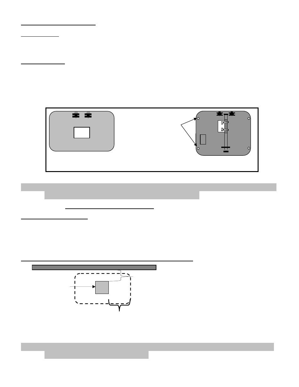
The operator base has four predrilled holes and four access holes, which are covered with press in hole plugs. These
holes are sized to accommodate ½ anchor bolts and the plugged hole will accept a standard size ¾ inch socket. Keep
the operator parallel with the gate while securing. See illustrations 9,13 and 14 for dimensions.
POST MOUNT:
The operator base is equipped with a four-inch post receiver located on the bottom of the base. This
receiver will accept a square or round four-inch post. Keep the operator parallel with the gate and level
while securing in place. See illustration 10 for dimensions.
Set the operator in place (pad or post). Ensure that the chain bolts once installed will be properly aligned with the chain
rollers, see illustrations 4 – 8. Once alignment is verified secure operator in place using bolts for pad installation and
welding for post installation. Keep the operator parallel with the gate while securing in place.
NOTE: Regardless of mounting method ensure that operator base does not extend into the
driveway area, where damage from traffic could occur.
STEP 1
Post Mount Installation
POST SPECIFICATIONS
Steel post is an optional mounting method. The type of post the operator is designed to handle is a 4-inch round or
square thick wall post. The operator can be installed directly onto the post or a steel frame can be constructed on the
top of post. If the method chosen is to construct a frame see dimensions in pad mount section (Illustrations 13,14) for
bolt locations and size. If the direct post mount option is chosen use the dimensions that follow to install, also consider
that additional bracing might be needed.
POST LOCATION TO GATE EDGE AND HOLE PREPARATION
Post must be parallel to gate edge. Hole depth should be at least 36 inches and bell shaped to reduce operator
movement to a minimum. The post must be concreted in place.
NOTE: Remember to mount the operator high enough above ground level so that the post
and operator can be welded securely.
GATE BOTTOM VIEW
8.75 inches
(measured from gate
edge to post edge.)
4” steel post
(round or square)
Illustration 10
Illustration 9
Anchor bolt
access holes
(4 places).
Use with pad
mount or
post mount
with frame.
Receiver
Post
Receiver post located on
bottom of operator
base.
When determining post location
ensure that the operator’s outer
edge is a safe distance away from
the drive to avoid damage from
traffic.
See illustration 13 for operator
base overall dimensions.
8.75 inches (measured from
operator edge to post edge)