Step 2 mounting of chain brackets to gate, Step 3 connecting chain – Controlled Products Systems Group PATRSL User Manual
Page 12
10
STEP 2 Mounting of Chain Brackets to Gate
With the operator securely mounted use the following procedure to locate and install gate brackets to gate
ends.
1.
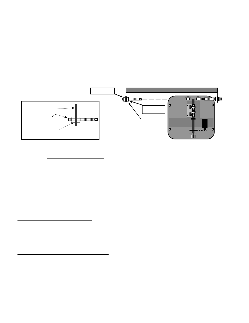
Install the chain adjustment bolt into the chain bracket as shown in illustration 15 below.
2. Slide the gate fully open. Using the diagram below locate the correct position for the gate bracket. Clamp
the bracket in place and repeat for gate in the fully closed position. Before welding gate brackets in place
refer to illustrations 4 – 8 to ensure correct installation. Once alignment is correct weld chain brackets in
place.
TOP VIEW (GATE FRAME 2”)
STEP 3 Connecting Chain
Using the master links supplied connect one end of chain to one of the chain adjustment bolts. Use additional
master links to connect chain together as needed to route chain through the operator (See Illustration 3,16).
In most installations the chain will have to be cut to the desired length. To determine the desired chain length
loosen the chain adjustment bolts to allow for maximum adjustment (illustration 15). Pull the emergency
release knob to allow the chain to roll freely through the operator. Pull the chain to mate up with the
remaining chain adjustment bolt and mark link that needs to be cut. Once link is cut install master link and
connect to chain adjustment bolt.
CHAIN TENSION ADJUSTMENT
The outer ½” nut on the chain adjustment bolt adjust chain tension, it is important not to over tighten the
chain or premature wear will result. It is also important not to allow the chain to be to loose. Once the chain
tension is correct secure the inner ½ inch nut by tightening it against the chain bracket. The chain will have a
few inches of drop across the span of the gate when correct.
GATE POSITION BEFORE OPERATING
After the chain is connected to the gate verify that the gate rolls freely from the fully open position to the
fully closed position. If any friction points exist they must be corrected. Open the gate to the center position
and push the emergency release knob back in place, it might be necessary to roll the gate while pushing the
knob back in place.
NOTE:
The gate must be in the center position (half open) at this time.
Illustration 16
Install chain adjustment
bolts as shown to allow
for maximum tension
adjustment.
Outer nut
Inner nut
Illustration 15
Chain Bracket
Chain Adjustment Bolt
½” Nut (2 plcs)