Parts and accessories, Specifi cations – GF Signet 2100 Turbine Flow Sensor User Manual
Page 2
Georg Fischer Signet LLC, 3401 Aerojet Avenue, El Monte, CA 91731-2882 U.S.A. • Tel. (626) 571-2770 • Fax (626) 573-2057
For Worldwide Sales and Service, visit our website: www.gfsignet.com • Or call (in the U.S.): (800) 854-4090
For the most up-to-date information, please refer to our website at www.gfsignet.com
3-2100.090-1 Rev. G 02/10 English
© Georg Fischer Signet LLC 2010
Cable Length:
4.6 m (15 ft) can be extended up to 300 m
(1000
ft)
Cable Type:
PVC jacketed, 2 conductor twisted pair with
shield
(22
AWG)
Standards and Approvals
CE
Manufactured under ISO 9001 and 14001
China RoHS (Go to www.gfsignet.com for details)
Environmental
Relative Humidity:
0 to 100%
Storage Temperature:
-15 ºC to 80 ºC (5 ºF to 176 ºF)
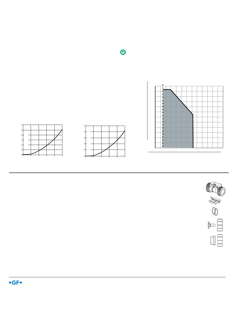
40
80
120
160
200
3
6
8
11
14
240
17
-4
-20
5
30
55
80
105
°F
°C
psi
bar
130
41
86
131
176
221
266
16 bar @ 0
°
C,7.4 bar @ 70
°
C
(232 psi @ 32
°
F, 134 psi @ 158
°
F)
¡
5. Parts and Accessories
Part No.
Code No.
Description
Turbine Body:
3-2100.390-1L
159.000.015
Replacement Lo Flow with FPM O-rings
3-2100.390-1H
159.000.016
Replacement Hi Flow with FPM O-rings
3-2100.390-2L
159.000.017
Replacement Lo Flow with EPR (EPDM) O-rings
3-2100.390-2H
159.000.018
Replacement Hi Flow with EPR (EPDM) O-rings
Electronics:
3-2100.390
159.000.014
Electronics Module with 4.6 m (15 ft) cable
O-rings:
1220-0018
159.000.019
O-rings (2) FPM
1224-0018
159.000.020
O-rings (2) EPR (EPDM)
Connector Kits:
3-2100-31
159.000.005
Hose Barb connector kit, PVDF, 1/2"
3-2100-32
159.000.006
Hose Barb connector kit, PVDF, 3/8"
3-2100-33
159.000.007
Hose Barb connector kit, PVDF, 1/4"
3-2100-34
159.000.008
Fusion Socket connector, PVDF, DN15
3-2100-35
159.000.009
Butt Fusion/IR connector kit, PVDF, DN15
3-2100-36
159.000.010
Metric Socket connector kit, PVC, DN15
3-2100-37
159.000.011
SCH 80 Socket connector kit, PVC, 1/2 in.
3-2100-38
159.000.012
NPT Thread Socket connector kit, PVC, 1/2 in.
3-8050-1
159 000 007
Universal junction box
4. Specifi cations
General
Operating Range: -L = 0.38 to 3.8 l/m (0.10 to 1 U.S. gpm)
-H = 3 to 38 l/m (0.8 to 10 U.S. gpm)
Pipe Size:
DN15 (1/2 in.)
Hose Size:
DN8 (1/4 in.), DN10 (3/8 in.), DN15 (1/2 in.)
Linearity:
±3% of reading
Repeatability:
±0.5% of reading
Weight:
151 g (0.33 lbs)
Wetted Materials
Sensor body/rotor: PVDF
Shaft/bearings: Ceramic
O-rings:
-1 = FPM, -2 = EPR (EPDM)
Electronics:
PBT (polybutylene terephthalate)
EVA (ethylene vinyl acetate)
Electrical
Electrical
Power:
5 to 24 VDC ± 10%, regulated, 1.5 mA max.
Reverse polarity protected
Output:
Open collector, sinking, max 30 mA
FLOW
Bar PSI
0.14 2.0
0.11 1.6
0.08 1.2
0.05 0.8
0.03 0.4
0
Flow
GPM 0 2 4 6 8 10
LPM
0 7.6 15.1 22.7 30.3 37.9
Pressure Drop - High Flow
Pressure Drop
Bar PSI
2.04 30
1.70 25
1.36 20
1.02 15
0.68 10
0.34 5
0
Flow
GPM 0 0.2 0.4 0.6 0.8 1.0
LPM 0 0.8 1.5 2.3 3.0 3.8
Pressure Drop - Low Flow
Pressure Drop
Maximum Pressure/Temperature