Installation – GF Signet 9900 H COMM Module User Manual
Page 2
2
9900 H COMM Module Instruction Sheet
If the 9900 Base Unit will be mounted in a panel, plug-in modules may
be installed either before or after the base unit is mounted. If the 9900
Base Unit will be mounted using the accessory wall mount bracket,
install plug-in modules fi rst. If the Direct Conductivity/Resistivity
Module will be included in your unit, install the H COMM module fi rst
and then install Conductivity/Resistivity Module over the H COMM
Module.
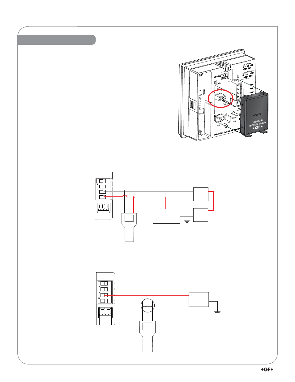
To install the H COMM module, carefully align the module pins into its
plug (see illustration) and push the module straight in until the tabs on
the bottom edge snap into place.
To uninstall, squeeze tabs, grasp the module and pull straight out.
3-9900.395
H COMM Module
DC Power
Loop V
oltage
–
+
+
–
PLC
Device
Optional ammeter
(recommended for
4 to 20 mA trim only)
Power
Supply
9900 Device
Connections
Loop +
Loop –
(Primary HART Master)
Hand-held device
(Secondary HART Master)
Red
Black
–
+
Power
Supply
Loop +
Loop –
250
Load Resistor
Hand-held device
(HART Master)
9900 Device
Connections
Red
Black
Connecting HART with a Loop-powered sensor
Connecting HART to a Hand-Held Master Device
Installation
(Typical installation)
(Typical installation)
Be careful not to bend the pins when installing or removing the
module to or from the base unit.