10 connecting the flow sensor to the transmitter, English, Fig. 24: wiring of the do2 and do3 relay outputs – Burkert Type 8025 User Manual
Page 28
28
Installation and wiring
Type 8025 UNIVERSAL
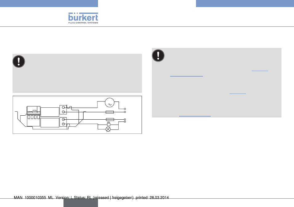
7.4.9 Wiring the relay outputs Do2 and
Do3 of the panel or a wall-mounted
version
Insert▶the▶supplied▶stopper▶gaskets▶into▶the▶unused▶cable▶
glands▶to▶ensure▶the▶tightness▶of▶the▶device.
•▶ Unscrew▶the▶unused▶cable▶gland.
•▶ Remove▶the▶transparent▶disk.
•▶ Insert▶the▶supplied▶stopper▶gasket.
•▶ Screw▶the▶nut▶of▶the▶cable▶gland.
FLOW
SENSOR
SUPPLY
NC
COIL
PULSE INPUT
NPN/PN
P
2
1
3
PE
+
-
DO2
DO3
OF
FO
N
230 V AC
m
3 A
3 A
230 V AC
Fig. 24: Wiring of the DO2 and DO3 relay outputs
7.4.10 connecting the flow sensor to the
transmitter
Before▶connecting▶the▶flow▶sensor▶to▶the▶transmitter▶8025▶
UNIVERSAL:
•▶ set▶selector▶"SENSOR▶TYPE"▶depending▶on▶the▶output▶
signal▶providing▶from▶▶the▶flow▶sensor.▶See▶„Fig.▶25“▶and▶
„Tab.▶1“▶page▶29.
•▶ if▶the▶selector▶"SENSOR▶TYPE"▶is▶set▶on▶"NPN/PNP",▶
set▶the▶selector▶"SENSOR▶SUPPLY"▶depending▶on▶the▶
transmitter▶supply▶voltage.▶See▶„Fig.▶26“.
•▶ set▶selector▶"LOAD"▶depending▶on▶the▶type▶of▶signal▶sent▶
out▶by▶the▶flow▶sensor▶and▶on▶the▶load▶wanted▶on▶terminal▶
1▶"PULSE▶INPUT"▶of▶terminal▶block▶"FLOW▶SENSOR".▶
See▶„Tab.▶1“▶page▶29.
English