2 terminal assignment and use of the selectors, Ac d, English – Burkert Type 8025 User Manual
Page 16: See▶ „fig.▶15“▶page▶21 switch, See▶chap. ▶„7.4.10“ switch, See▶ „tab.▶1“▶page▶29 switch
16
Installation and wiring
Type 8025 UNIVERSAL
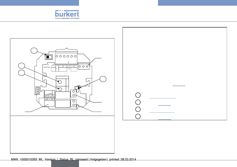
7.4.2 Terminal assignment and use of the
selectors
2
B
1
5
A
C
D
CURRENT
SOURCE
SINK
BINARY
PE
PE
PE
PE
DI1
DI2
DI3
DI4
DO4
ISOG
FLOW
SENSOR
L+
L-
PE P- P+
NC
Iout
PULSE
DO1
Supply
12..36Vdc
Univ
Batch
(AO1)
SUPPLY
NC
COIL
PULSE INPUT
NPN/PN
P
2
1
3
PE
+
-
SENSOR
SUPPL
Y
LOAD
+5V
L+
(L+)-12V
COIL/PNP
39K
470
2.2K
SENSOR TYPE
COIL
NPN/PNP
DO2
DO3
OFF
ON
3
4
terminal block 1
•▶ Iout:▶4-20▶mA▶output▶(AO1)
•▶ L+:▶V+▶(positive▶voltage)
•▶ L-:▶0V▶(power▶supply▶ground)
•▶ PE:▶protective▶earth,▶factory▶wired
•▶ P-:▶Negative▶transistor▶output▶(DO1)
•▶ P+:▶Positive▶transistor▶output▶(DO1)
terminal block 2
PE:▶Shieldings▶of▶both▶the▶power▶supply▶cable▶and▶the▶AO1▶and▶
DO1▶output▶cables
terminal block 3:▶Wiring▶of▶the▶relay▶output▶DO2▶(if▶the▶device▶
has▶relays).
terminal block 4:▶Wiring▶of▶the▶relay▶output▶DO3▶(if▶the▶device▶
has▶relays).
terminal block 5 "flow sensor": Wiring▶the▶remote▶flow▶
sensor.▶The▶wiring▶depends▶on▶the▶type▶of▶output▶signal▶originating▶
from▶the▶flow▶sensor:▶see▶chap.▶„7.4.10“.
Switch▶
A
:▶see▶„Fig.▶15“▶page▶21
Switch▶
B
:▶see▶chap.▶„7.4.10“
Switch▶
C
:▶see▶„Tab.▶1“▶page▶29
Switch▶
D
:▶see▶chap.▶„7.4.10“
Fig. 9: Terminal assignment of a panel version or a wall-mounted
version, 12-36 V DC
English