4 wiring, 3 installation of a wall-mounted version, English – Burkert Type 8025 User Manual
Page 13: Current source sink, Ao1) supply nc coil pulse input npn/pnp 2 1 3 pe, Fig. 6: installation of a wall-mounted version, Wire▶acc.▶to▶instructions▶in▶chap.▶ „7.4, Remove▶the▶blanking▶strips▶covering▶the▶screws
13
Installation and wiring
Type 8025 UNIVERSAL
1
1
1
1
106 mm
230V
L N
230V
T 250 mA
5 6 7 8 9 10
L N
230V
CURRENT
SOURCE
SINK
BINARY
PE
PE
PE
PE
DI1
DI2
DI3
DI4
DO4
ISOG
FLOW
SENSOR
L+
L-
PE P- P+
NC
Iout
PULSE
DO1
Supply
12..36Vdc
Univ
Batch
(AO1)
SUPPLY
NC
COIL
PULSE INPUT
NPN/PNP
2
1
3
PE
+
-
SENSOR
SUPPL
Y
LOAD
+5V
L+
(L+)-12V COIL/PNP
39K
470
2.2K
SENSOR TYPE
COIL
NPN/PNP
DO2
DO3
OF
FO
N
106 mm
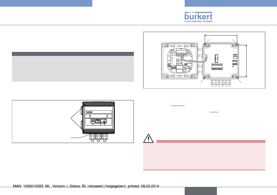
Fig. 6: Installation of a wall-mounted version
▶
→
Secure▶the▶housing▶to▶the▶support▶respecting▶the▶dimensions▶
indicated▶in▶„Fig.▶6“.
▶
→
Wire▶acc.▶to▶instructions▶in▶chap.▶„7.4“.
▶
→
Close▶the▶housing▶and▶tighten▶the▶4▶screws▶of▶the▶cover.
7.4
Wiring
danger
risk of injury due to electrical voltage.
▶
▶ Shut▶down▶the▶electrical▶power▶source▶of▶all▶the▶conductors▶and▶
isolate▶it▶before▶carrying▶out▶work▶on▶the▶system.
▶
▶ Observe▶all▶applicable▶accident▶protection▶and▶safety▶regula-
tions▶for▶electrical▶equipment.
7.3
Installation of a wall-mounted
version
note
risk of material damage if the cable glands are not tightly
screwed on the housing
▶
▶ Before▶installing▶the▶wall-mounted▶housing▶on▶its▶support,▶
tighten▶the▶nuts▶of▶the▶entry▶item▶of▶the▶cables▶glands▶at▶a▶torque▶
of▶1.5▶Nm.
The▶flow▶transmitter▶in▶a▶wall-mounted▶version▶has▶4▶holes▶in▶the▶
bottom▶of▶the▶housing.
▶
→
Remove▶the▶blanking▶strips▶covering▶the▶screws.
Blanking▶strips
ENTER
0....9
FLOW
Nut▶of▶the▶entry▶item
▶
→
Loosen▶the▶4▶screws▶and▶open▶the▶cover▶to▶get▶access▶to▶the▶holes▶[1].
English