English, Set▶the – Burkert Type 8025 User Manual
Page 22
22
Installation and wiring
Type 8025 UNIVERSAL
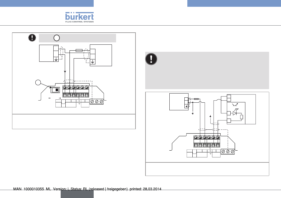
A
CURRENT
SOURCE
SINK
PE
PE
PE
L+
L-
PE P- P+
NC
Iout
PULSE
DO1
Supply
12..36Vdc
Univ
Batch
(AO1)
12-36 V DC
+
-
300 mA
I
+
-
(*)
Power▶supply
4-20mA▶input▶at▶external▶
instrument
Set▶the▶
A
▶
switch▶on▶the▶right.
*)▶If▶a▶direct▶earth▶connection▶is▶not▶possible,▶fit▶a▶100▶nF/50▶V▶
capacitor▶between▶the▶negative▶power▶supply▶terminal▶and▶the▶earth
Fig. 17: Wiring of the 4-20 mA output (AO1) in sinking mode
7.4.6 Wiring the Do1 transistor output of
a panel version or a wall-mounted
version, 12-36 V Dc
Insert▶the▶supplied▶stopper▶gaskets▶into▶the▶unused▶cable▶
glands▶to▶ensure▶the▶tightness▶of▶the▶device.
•▶ Unscrew▶the▶unused▶cable▶gland.
•▶ Remove▶the▶transparent▶disk.
•▶ Insert▶the▶supplied▶stopper▶gasket.
•▶ Screw▶the▶nut▶of▶the▶cable▶gland.
PE
PE
PE
L+
L-
PE P- P+
NC
Iout
PULSE
DO1
Supply
12..36Vdc
Univ
Batch
(AO1)
300 mA
+
-
12-36 V DC
(*)
+
-
+
- 5-36 VDC
PLC
Power▶supply▶of▶
the▶device
*)▶If▶a▶direct▶earth▶connection▶is▶not▶possible,▶fit▶a▶100▶nF/50▶V▶
capacitor▶between▶the▶negative▶power▶supply▶terminal▶and▶the▶earth
Fig. 18: NPN wiring of the DO1 transistor output
English