Burkert Type 8025 User Manual
Page 20
20
Installation and wiring
Type 8025 UNIVERSAL
▶
→
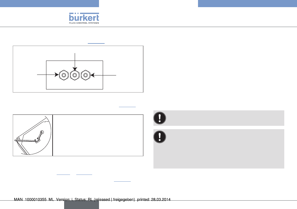
Insert▶each▶cable▶through▶a▶nut▶than▶through▶the▶cable▶gland,▶
using▶the▶cable▶glands▶as▶shown▶in▶„Fig.▶13“.
Flow▶sensor▶cable
Cables▶of▶the▶outputs
Power▶supply▶cable▶
12-36▶V▶DC▶or▶
115/230▶V▶AC
Fig. 13: Using the cable glands
▶
→
Remove▶the▶two▶terminal▶blocks▶(marked▶6▶and▶7▶in▶„Fig.▶10“)▶
from▶the▶housing.
▶
→
Before▶wiring▶the▶device▶insert▶the▶sup-
plied▶cable▶clips▶into▶the▶slots▶of▶the▶elec-
tronic▶board▶and▶of▶the▶115/230▶V▶AC▶
power▶supply▶board▶if▶the▶device▶has▶such▶
a▶board.
Fig. 14: Inserting the cable clips
▶
→
Depending▶on▶the▶operating▶voltage▶of▶the▶device,▶wire▶
according▶to▶chap.▶„7.4.5“▶to▶„7.4.10“.
▶
→
Insert▶the▶two▶terminal▶blocks▶(marked▶6▶and▶7▶in▶„Fig.▶10“)▶into▶
their▶original▶position.
▶
→
Letting▶the▶housing▶stay▶completely▶open,▶secure▶the▶power▶
supply▶cable,▶the▶flow▶sensor▶connection▶cable▶and,▶depending▶
on▶the▶version,▶the▶relay▶connection▶cables,▶with▶the▶cable▶clips.
▶
→
Tighten▶the▶cable▶glands▶making▶sure▶the▶cable▶in▶the▶housing▶is▶
long▶enough▶to▶allow▶complete▶opening▶of▶the▶housing.
▶
→
Close▶the▶cover.
▶
→
Tighten▶the▶4▶screws.
▶
→
Put▶the▶blanking▶strips▶on▶the▶housing.
7.4.5 Wiring the Ao1 current output of a
panel version or a wall-mounted
version, 12-36 V Dc
Only▶move▶the▶selectors▶when▶the▶power▶supply▶is▶off.
Insert▶the▶supplied▶stopper▶gaskets▶into▶the▶unused▶cable▶
glands▶to▶ensure▶the▶tightness▶of▶the▶device.
•▶ Unscrew▶the▶unused▶cable▶gland.
•▶ Remove▶the▶transparent▶disk.
•▶ Insert▶the▶supplied▶stopper▶gasket.
•▶ Screw▶the▶nut▶of▶the▶cable▶gland.
The▶4-20▶mA▶output▶can▶be▶wired▶in▶either▶sourcing▶or▶sinking▶
mode.
English