English, 2 setting the station addresses, 3 led display – Burkert Type 8642 User Manual
Page 17: 4 watchdog
16 - 8642
english
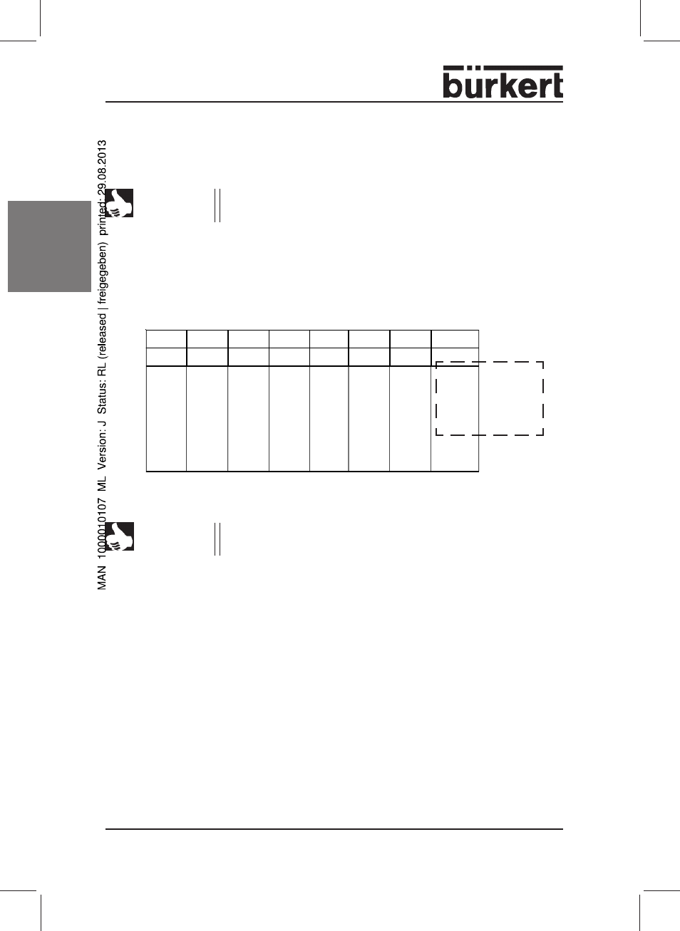
5.2.2 Setting the Station Addresses
DIP switch 1 to 7
Bit 1 to Bit 7
NOTE
The DIP switches are only read in when the unit is switched on.
In the PROFIBUS PA, each station is given an address. These addresses are
set up using the DIP switches 1 to 7.
The permissible address range lies between 3 and 124
Settings:
NOTE
If switch 8 is in the ON position, the internal address is used!
This address can be set up via the field bus.
permitted
address range
3 ... 124
5.2.3 LED Display
The LED flashes when the device is engaged in cyclic data communication.
The LED lights briefly on connecting the device.
If the device detects an internal error, the LED remains lit.
5.2.4 Watchdog
In order to recognize errors better, we recommend operating the device in
cyclic data communication with „DP watchdog“.
* Delivery state: Address 126
2
0
2
1
2
2
2
3
2
4
2
5
2
6
DIP-1
DIP-2
DIP-3
DIP-4
DIP-5
DIP-6
DIP-7
Address
ON
ON
OFF
OFF
OFF
OFF
OFF
3
:
:
OFF
OFF
ON
ON
ON
ON
ON
124
ON
OFF
ON
ON
ON
ON
ON
125
OFF
ON
ON
ON
ON
ON
ON
126*