Brooks – Brooks Instrument GF81 User Manual
Page 45
4-7
Brooks
®
GF40/GF80/GF81 Devices
Installation and Operation Manual
X-TMF-GF40-GF80-Series-MFC-eng
Part Number: 541B161AAG
June, 2013
Section 4 Maintenance & Troubleshooting
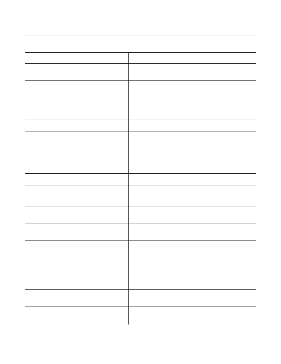
Symptoms & Possible Causes
Corrective Action
7. OEM tool does not read correct
GF40/GF80/GF81
Series zero reading.
Is the differential pressure across the
GF40/GF80/GF81
Series valve leakage.
GF40/GF80/GF81
Series really zero?
Incorrect MFC zero.
Is the supply voltage within specified range?
Is the
GF40/GF80/GF81
Series mounted in the proper
attitude? Is the flow output signal of the
GF40/GF80/GF81
Series really zero?
8. Zero Drift.
Improper zero of the
GF40/GF80/GF81
Series?
GF40/GF80/GF81
Series aging or sensor stabilization.
Excessive Valve leakage?
Zero is not correct.
9. Calibration Drift.
Gas box temperature too high?
Zero is not correct.
Is it linear offset?
10.
GF40/GF80
Series indicates Overshoot.
If the tool is idle for an extended period of time,
Purge the line before operating.
high inlet pressure or contamination will cause
overshoot on first use.
11.OEM tool indicates the wrong full scale
value for
GF40/GF80
Series.
Older version of Multiflo Configurator used
Update Multiflo Configurator.
Refer to Section 2-17.
to program
GF40/GF80
Series.
12.
GF40/GF80/GF81
Series dumps large
volume of gas into chamber when setpoint is
commanded from the tool.
The tool is commanding a setpoint before the
Change the tool sequence.
pneumatic valves are opened.
GF40/GF80/GF81
Series and pneumatic timing may
be offset.
GF40/GF80/GF81
Series overshoots.
13. Tool display output doesn’t match
GF40/GF80/GF81
Series flow output.
Cable resistance or read-out impedance causing
Check cables and read out. Eliminate any ground loops.
offset in the tool’s display.
Table 4-2 GF40/GF80/GF81 Series Troubleshooting Guide (Continued)