Brooks – Brooks Instrument GF81 User Manual
Page 16
1-10
Brooks
®
GF40/GF80/GF81 Devices
Installation and Operation Manual
X-TMF-GF40-GF80-Series-MFC-eng
Part Number: 541B161AAG
June, 2013
Section 1 Introduction
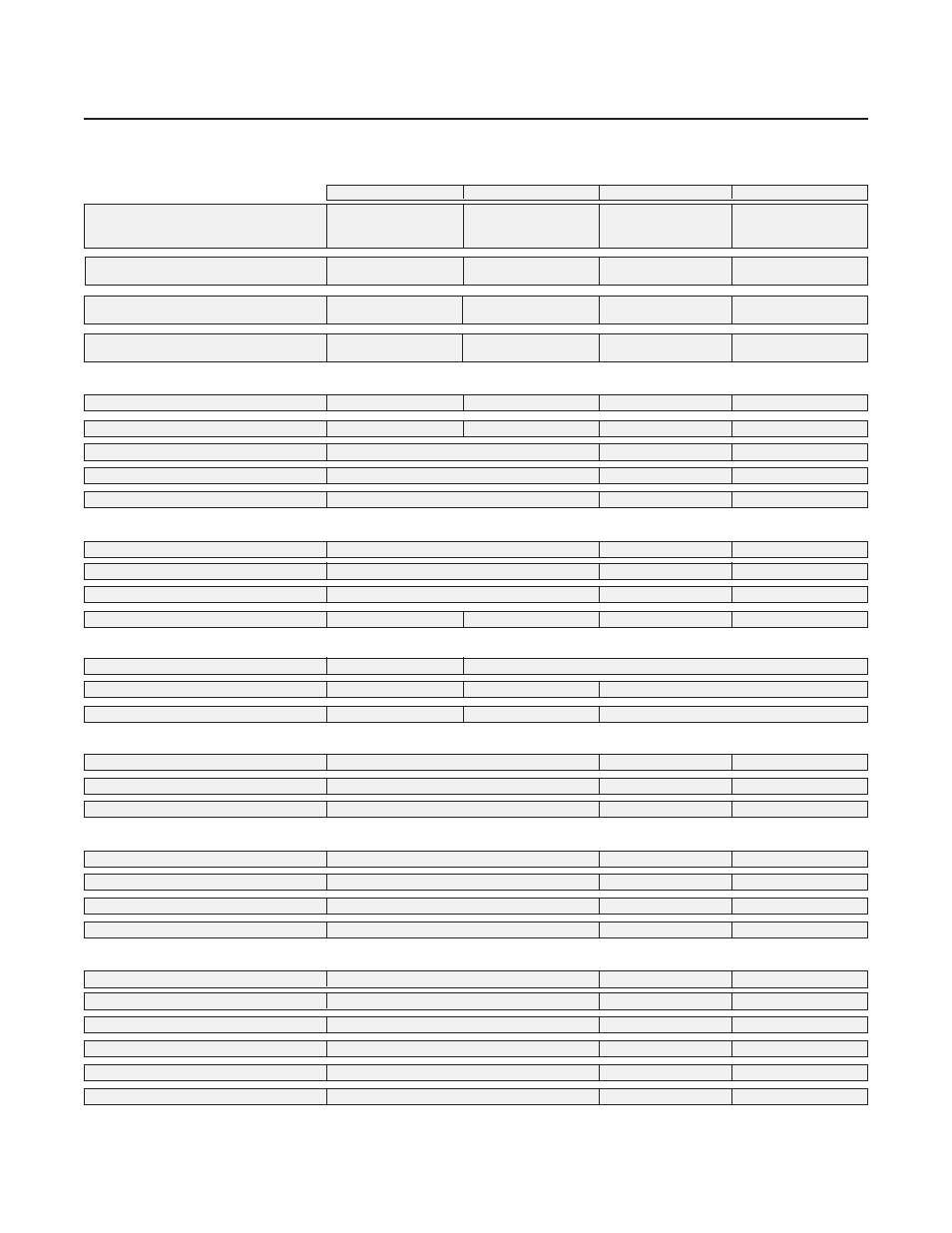
Table 1-5 GF40/GF80/GF81 Electrical Specifications
Communication Pr
Communication Pr
Communication Pr
Communication Pr
Communication Protocol
otocol
otocol
otocol
otocol
RS485
RS485
RS485
RS485
RS485
Pr
Pr
Pr
Pr
Profibus
ofibus
ofibus
ofibus
ofibus
DeviceNet
DeviceNet
DeviceNet
DeviceNet
DeviceNet
EtherCA
EtherCA
EtherCA
EtherCA
EtherCATTTTT
Electrical Connection
Electrical Connection
Electrical Connection
Electrical Connection
Electrical Connection
1 x 15-pin Male Sub-D,
1 x 15-pin Male Sub-D/
1 x M12 with
5-pin M8 with
(A)
1 x 9-pin Female
threaded coupling nut
threaded coupling nut/
Sub-D
(B)
2 x RJ45
Analog I/O
Analog I/O
Analog I/O
Analog I/O
Analog I/O
0-5 V, 0-10 V,
0-5 V, 0-20 mA,
0-5 V
0-5 V
0-20 mA, 4-20 mA
4-20 mA
GF40/GF80 P
GF40/GF80 P
GF40/GF80 P
GF40/GF80 P
GF40/GF80 Power Max./Pur
ower Max./Pur
ower Max./Pur
ower Max./Pur
ower Max./Purge
ge
ge
ge
ge
From +12 Vdc to
From +13.5 Vdc to
From +11 Vdc to
From +13.5 Vdc to
+24 Vdc: 7 Watt/8 Watt
+27 Vdc: 7 Watt/8 Watt
+25 Vdc: 7 Watt/8 Watt
+27 Vdc: 7 Watt/8 Watt
GF81 P
GF81 P
GF81 P
GF81 P
GF81 Power Max./Pur
ower Max./Pur
ower Max./Pur
ower Max./Pur
ower Max./Purge
ge
ge
ge
ge
From +12 Vdc to
From +13.5 Vdc to
From +11 Vdc to
N/A
+24 Vdc: 3.3 Watt/10.2 Watt +27 Vdc: 3.3 Watt/10.2 Watt +25 Vdc: 3.3 Watt/10.2 Watt
VVVVVoltage Set P
oltage Set P
oltage Set P
oltage Set P
oltage Set Poin
oin
oin
oin
oint Input Specification
t Input Specification
t Input Specification
t Input Specification
t Input Specification
Nominal Range
Nominal Range
Nominal Range
Nominal Range
Nominal Range
0-5 Vdc or 0-10 Vdc
0-5 Vdc
N/A
N/A
Full Range
Full Range
Full Range
Full Range
Full Range
0-11 Vdc
0-5.5 Vdc
N/A
N/A
Absolute Max.
Absolute Max.
Absolute Max.
Absolute Max.
Absolute Max.
25 V (without damage)
N/A
N/A
Input Impedence
Input Impedence
Input Impedence
Input Impedence
Input Impedence
192 kOhms
N/A
N/A
Requir
Requir
Requir
Requir
Required Max. Sink Curr
ed Max. Sink Curr
ed Max. Sink Curr
ed Max. Sink Curr
ed Max. Sink Curren
en
en
en
enttttt
0.002 mA
N/A
N/A
Curr
Curr
Curr
Curr
Curren
en
en
en
ent Set P
t Set P
t Set P
t Set P
t Set Poin
oin
oin
oin
ointtttt
Nominal Range
Nominal Range
Nominal Range
Nominal Range
Nominal Range
4-20 mA or 0-20 mA
N/A
N/A
Full Range
Full Range
Full Range
Full Range
Full Range
0-22 mA
N/A
N/A
Absolute Max.
Absolute Max.
Absolute Max.
Absolute Max.
Absolute Max.
25 mA (without damage)
N/A
N/A
Input Impedence
Input Impedence
Input Impedence
Input Impedence
Input Impedence
250 Ohms
125 Ohms
N/A
N/A
Flow Output (V
Flow Output (V
Flow Output (V
Flow Output (V
Flow Output (Voltage) Specifications
oltage) Specifications
oltage) Specifications
oltage) Specifications
oltage) Specifications
Nominal Range
Nominal Range
Nominal Range
Nominal Range
Nominal Range
0-5 Vdc or 0-10 Vdc
0-5 Vdc
Full Range
Full Range
Full Range
Full Range
Full Range
(-0.5)-11 Vdc
0-5.5 Vdc
(-0.5)-5.5 Vdc
Min Load Resistance
Min Load Resistance
Min Load Resistance
Min Load Resistance
Min Load Resistance
1 kOhms
1 kOhms
0.5 kOhms
Flow Output (Curr
Flow Output (Curr
Flow Output (Curr
Flow Output (Curr
Flow Output (Curren
en
en
en
ent) Specifications
t) Specifications
t) Specifications
t) Specifications
t) Specifications
Nominal Range
Nominal Range
Nominal Range
Nominal Range
Nominal Range
0-20 mA or 4-20 mA
N/A
N/A
Full Range
Full Range
Full Range
Full Range
Full Range
0-22 mA (@ 0-20 mA); 3.8-22 mA (@ 4-20 mA)
N/A
N/A
Max. Load
Max. Load
Max. Load
Max. Load
Max. Load
400 Ohms (for supply voltage: 12-24 Vdc
N/A
N/A
Analog I/O
Analog I/O
Analog I/O
Analog I/O
Analog I/O Alarm Ouput*
Alarm Ouput*
Alarm Ouput*
Alarm Ouput*
Alarm Ouput*
TTTTType
ype
ype
ype
ype
Open Collector
N/A
N/A
Max. Closed (On) Curr
Max. Closed (On) Curr
Max. Closed (On) Curr
Max. Closed (On) Curr
Max. Closed (On) Curren
en
en
en
enttttt
25 mA
N/A
N/A
Max. Open (Off) Leakage
Max. Open (Off) Leakage
Max. Open (Off) Leakage
Max. Open (Off) Leakage
Max. Open (Off) Leakage
1
μA
N/A
N/A
Max. Open (Off)
Max. Open (Off)
Max. Open (Off)
Max. Open (Off)
Max. Open (Off) VVVVVoltage
oltage
oltage
oltage
oltage
30 Vdc
N/A
N/A
Analog I/O
Analog I/O
Analog I/O
Analog I/O
Analog I/O VVVVValve Override Signal Specifications**
alve Override Signal Specifications**
alve Override Signal Specifications**
alve Override Signal Specifications**
alve Override Signal Specifications**
Floating/Unconnected
Floating/Unconnected
Floating/Unconnected
Floating/Unconnected
Floating/Unconnected Instrument controls valve to command set point
N/A
N/A
VVVVVOR < 1.40
OR < 1.40
OR < 1.40
OR < 1.40
OR < 1.40 VVVVVdc
dc
dc
dc
dc
Valve Closed
N/A
N/A
1.70
1.70
1.70
1.70
1.70 VVVVVdc <
dc <
dc <
dc <
dc < VVVVVOR < 2.90
OR < 2.90
OR < 2.90
OR < 2.90
OR < 2.90 VVVVVdc
dc
dc
dc
dc
Valve Normal
N/A
N/A
VVVVVOR > 3.20
OR > 3.20
OR > 3.20
OR > 3.20
OR > 3.20 VVVVVdc
dc
dc
dc
dc
Valve Open
N/A
N/A
Input Impedence
Input Impedence
Input Impedence
Input Impedence
Input Impedence
800 kOhms
N/A
N/A
Absolute Max. Input
Absolute Max. Input
Absolute Max. Input
Absolute Max. Input
Absolute Max. Input
(-25 Vdc) < VOR < 25 Vdc (without damage)
N/A
N/A
*The Alarm Output is an open collector or "contact type" that is CLOSED (on) whenever an alarm is active. The Alarm Output may be set to indicate any one of
various alarm conditions.
** The Valve Override Signal (VOR) is implemented as an analog input which measures the voltage at the input and controls the valve based upon the
measured reading as shown in this section.