Brooks – Brooks Instrument GF81 User Manual
Page 24
2-4
Brooks
®
GF40/GF80/GF81 Devices
Installation and Operation Manual
X-TMF-GF40-GF80-Series-MFC-eng
Part Number: 541B161AAG
June, 2013
Section 2 Installation
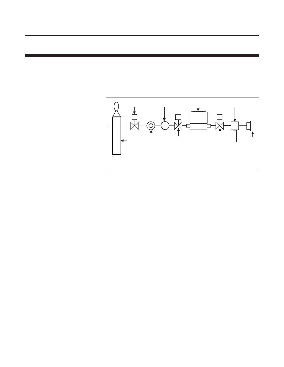
2-10 Flow Controller Installation Arrangement
Typical gas supply arrangements are shown in Figure 2-1. GF40s/GF80s/
GF81s are often arranged inside a gas panel. Configure standard
configurations ("SAs") or "blanks" for a variety of pure gases and mixtures.
As a result, MultiFlo technology enables the user to reduce unique
inventory requirements.
Figure 2-1 Typical Gas Supply Arrangement
2
4
8
9
7
5
3
1
1. Gas Source
2. Regulated Gas Supply
3. Point of Use (POU) Regulator
4
5. Upstream Shut-Off Valve
. Filter
6. GF40 or GF80
7. Downstream Shut-Off Valve
8. Tool
9. Vacuum Pump
6