Brooks – Brooks Instrument 5850EM User Manual
Page 60
4-10
Brooks
®
Models 5964, 5850EM
Section 4 Maintenance
Installation and Operation Manual
X-TMF-5964-5850EM-MFC-eng
Part Number: 541B121AHG
November, 2008
4-4 Orifice Sizing
The Orifice Sizing Nomograph, Figure 4-1, is used to calculate the control
valve's orifice size when changing any or all of the following factors from
the original factory calibration:
gas
operating pressure (inlet and outlet)
flow range
The flow controller's orifice is factory-sized to a preselected gas, operating
pressure and flow range. Note that the orifice is marked with its size in
thousandths of an inch. When changing the aforementioned factors,
calculate the new orifice size by following the procedure and example
outlined in the following paragraphs.
Example: Determine the orifice size for the following conditions:
Gas:
Hydrogen
Flow Rate:
2,000 sccm
Outlet Pressure: 30 psig
Inlet Pressure:
50 psig
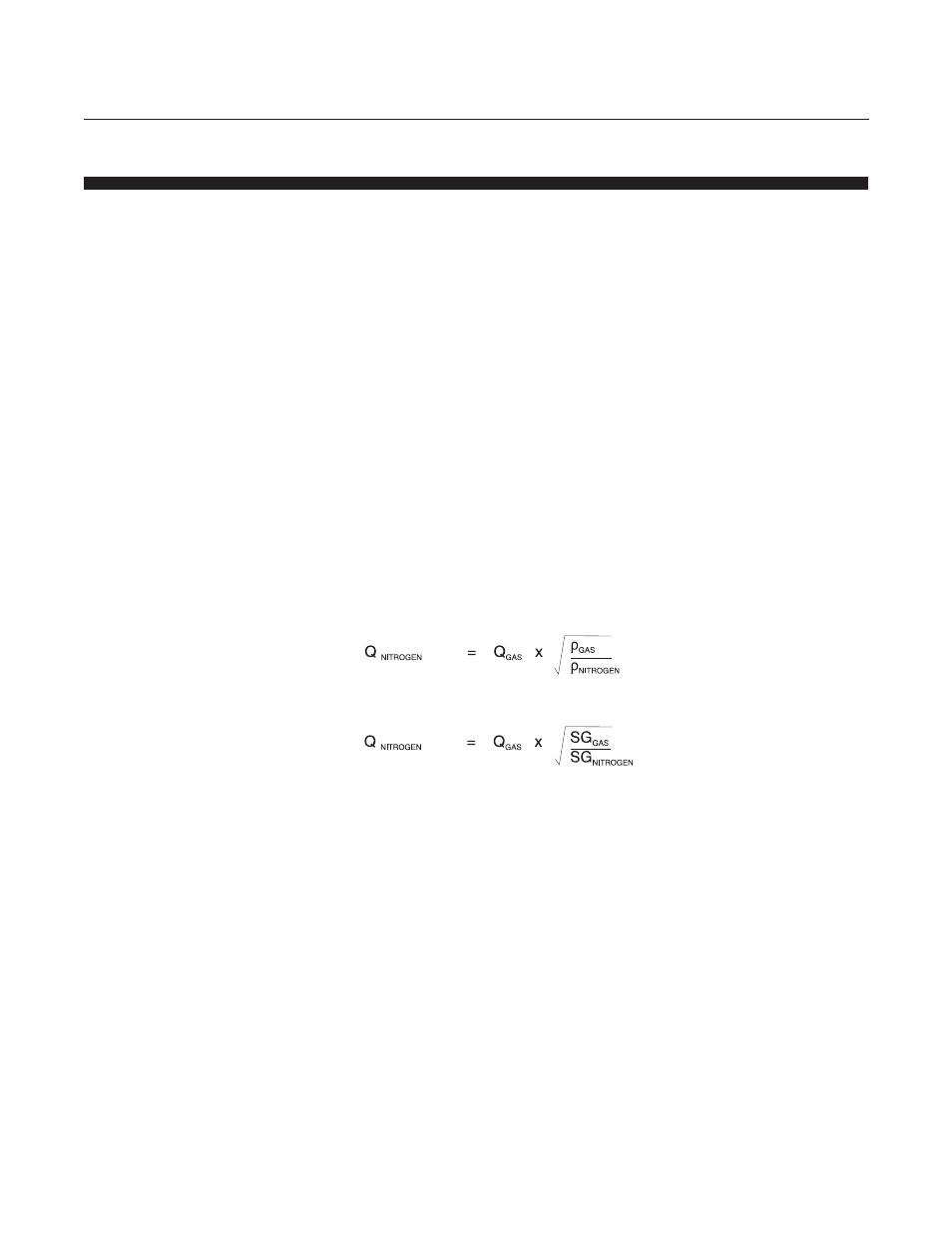
1. Determine Nitrogen equivalent flow rate (refer to Table 4-3).
OR
Where:
Q
NITROGEN
=
Nitrogen equivalent flow rate (sccm)
Q
GAS
=
Desired flow rate of the gas (sccm)
ρρρρρ
NITROGEN
=
Density of Nitrogen at 70°F
ρρρρρ
GAS
=
Density of the gas (taken at customer temperature)
SG
GAS
=
Specific gravity of the gas (taken at customer
temperature)
Refer to Table 4-5 for densities.