Brooks – Brooks Instrument 5850EM User Manual
Page 45
3-21
Brooks
®
Models 5964, 5850EM
Section 3 Operation
Installation and Operation Manual
X-TMF-5964-5850EM-MFC-eng
Part Number: 541B121AHG
November, 2008
g. Set the command potentiometer for zero percent of flow. Connect the
DVM positive lead to flow signal output (Pin 3 Card Edge, Pin 2 D-
Connector) and the negative lead to TP4 (circuit common). Readjust
the zero potentiometer for an output of zero mV ±2 mV as necessary.
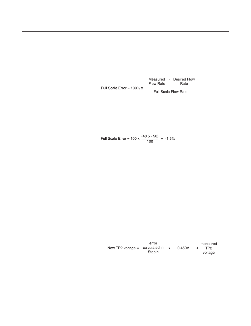
h. Set the command potentiometer for 50% of flow (2.500 V) and measure
the flow rate. Calculate the error as a percentage of full scale.
Example:
What is the percent of full scale error when full scale is equal to 100
sccm?
Measured flow rate = 48.5 sccm
Desired flow rate = 50.0 sccm
i. Calculate the TP2 correction voltage:
error calculated in Step h x 0.450 Volts
Example:
Error = -1.5%
TP2 correction voltage = -1.5 x 0.450 = -0.675 Volts
New TP2 voltage = zero volts + (-0.675) = -0675 Volts
j. Set the command potentiometer for 100% flow (5.000 V). Connect the
DVM positive lead to TP2 (linearity voltage) and the negative lead to
TP4 (circuit common).
k. Adjust the linearity potentiometer for an output equal to the new calcu-
lated TP2 voltage.
l. Repeat Steps f, g and h.
l1. If the error calculated in Step h is less than 0.5%, then the calibration
procedure is complete.
l2. If the error is greater than 0.5%, set the command potentiometer for
100% (5.000 V). Connect the DVM positive lead to TP2 (linearity
voltage) and the negative lead to TP4 (circuit common). Calculate a
new TP2 voltage as follows employing the measured TP2 voltage:
Example:
Controller error = 0.7%
Measured TP2 voltage = -0.567 Volts
TP2 correction = 0.7 x 0.450 = 0.315 Volts
New TP2 correction = 0.315 + (-0.567) = -0.252 Volts
Adjust the linearity potentiometer for an output equal to the new TP2
correction voltage and then repeat Steps f, g and h.