Brooks, Table 4-1 bench troubleshooting – Brooks Instrument 5850EM User Manual
Page 54
4-4
Brooks
®
Models 5964, 5850EM
Section 4 Maintenance
Installation and Operation Manual
X-TMF-5964-5850EM-MFC-eng
Part Number: 541B121AHG
November, 2008
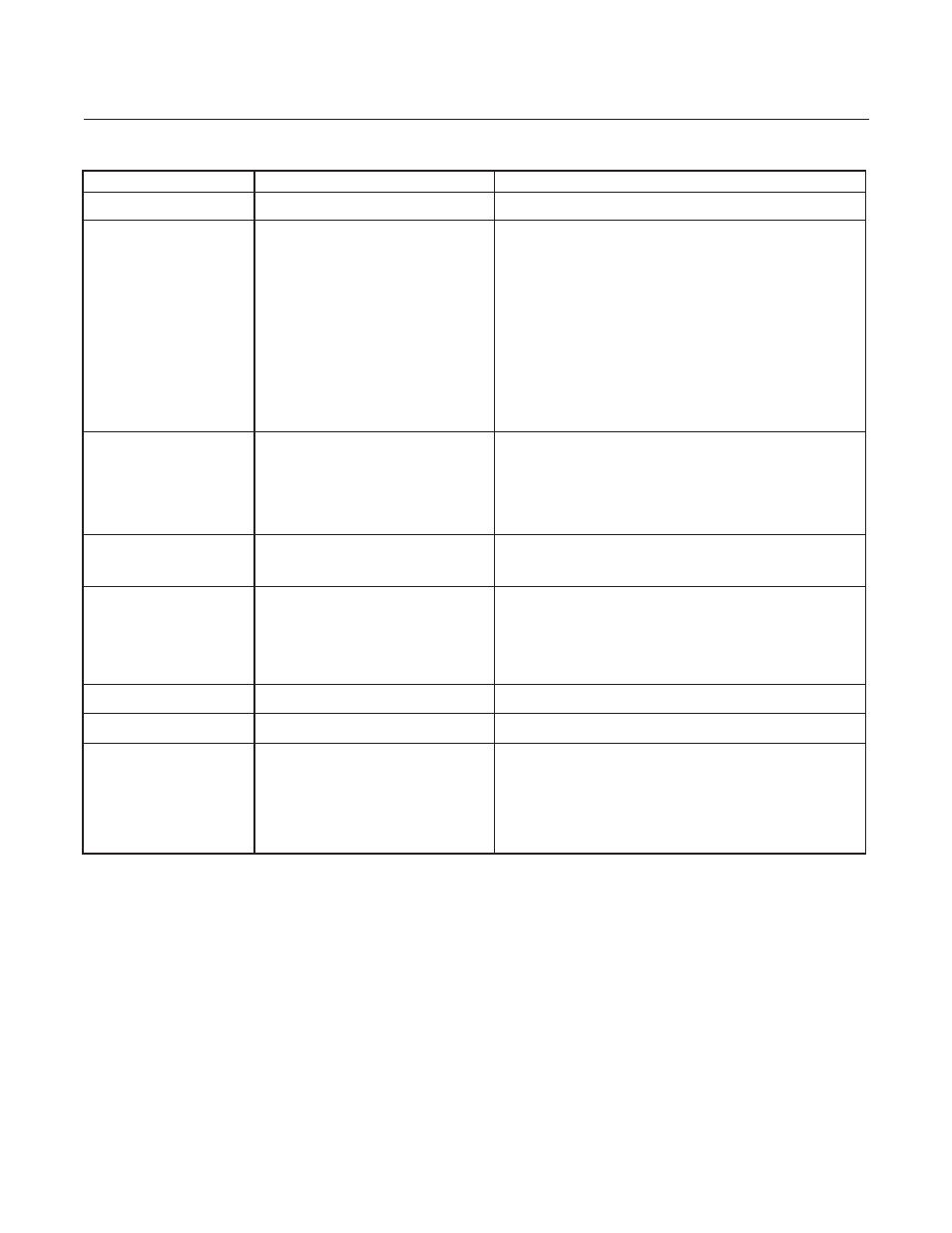
Table 4-1 Bench Troubleshooting
Trouble
Possible Cause
Check/Corrective Action
Actual flow overshoots setpoint by
Anticipate potentiometer out of adjustment.
Adjust anticipate potentiometer. Refer to Sections 3-5 & 3-8 .
more than 5% full scale.
Output stays at zero level regardless
Clogged Sensor tube and restrictor and/or a
Clean sensor. Refer to cleaning procedure, Section 4-2D.
of command and there is no flow
clogged orifice.
through the controller.
Closed or clogged flow path up- or downstream or
Open valve(s). Clean filter(s). Remove any foreign material from gas delivery system.
the controller.
Clogged Control Valve.
Check TP3 with the command at 100%. If the voltage is more negative than -11V,
disassemble and repair the control valve. Refer to Sections 4-3 and 4-4.
Internal reference being used as the command
Refer to Section 3-4.
source and the yellow jumper is in the wrong
position.
-15 volts applied to the valve override input
Check valve override input. Refer to Section 2-6 for terminal assignments.
Defective printed circuit board.
Replace printed circuit board. Refer to Section 4-3.
Valve voltage not returned, Pin L at common.
Check jumper for external valve return. Refer to Section 3-4.
"Valve-off" pin grounded.
Check "Valve-Off" input. Refer to Section 2-6 for terminal assignments.
Output signal stays at +6.8 Volts
Valve stuck open or leaky.
Clean and/or adjust control valve. Refer to cleaning procedure and/or Section 4-2D.
(26 mA for Current I/O Vers.) regard-
less of command and there is flow
+15 Volts applied to the valve override input.
Check the valve override terminal. Refer to Section 2-6 for terminal assignments.
through the controller.
Defective printed circuit board.
Replace printed circuit board. Refer to Section 4-3.
Command input floating.
Connect command signal. Refer to Section 2-6 for terminal assignments.
Pin D connected to common.
Remove Pin D from common.
Output signal follows set-point at
Leaky control valve
Disassemble and repair valve. Refer to Section 4-3.
higher commands but will not go to
zero.
Excessive resistance in valve voltage return line.
Reduce wiring resistance or reconfigure controller for "External Valve Return." Refer
to Section 3-4.
Output signal follows set-point at
Insufficient inlet pressure or pressure drop.
Adjust pressures, inspect in-line filters and clear/replace as necessary.
lower commands but does not reach
full scale.
Partially clogged sensor
Check calibration. Refer to Section 3-7.
Partially clogged valve.
Disassemble and repair control valve. Refer to Section 4-3.
Valve out of adjustment.
Adjust valve. Refer to Section 4-4.
Valve guide spring failure.
Check valve spring.
Controller grossly out of calibration.
Partially clogged sensor.
Clean sensor. Refer to the cleaning procedure, Section 4-2D.
Flow is higher than desired.
Controller grossly out of calibration.
Partially clogged restrictor.
Replace restrictor. Refer to Section 4-3.
Flow is lower than desired.
Controller oscillates.
Pressure drop or inlet pressure excessive.
Adjust pressures.
Oversized orifice.
Check orifice size. Refer to Section 4-6.
Valve out of adjustment.
Adjust valve. Refer to Section 4-4.
Anticipate potentiometer out of adjustment.
Adjust anticipate potentiometer. Refer to Section 3-8.
Faulty pressure regulator.
Check regulator output.
Defective printed circuit board.
Replace printed circuit board. Refer to Section 4-3.