Brooks, R3 r2 r1 r4 – Brooks Instrument 5850EM User Manual
Page 35
3-11
Brooks
®
Models 5964, 5850EM
Section 3 Operation
Installation and Operation Manual
X-TMF-5964-5850EM-MFC-eng
Part Number: 541B121AHG
November, 2008
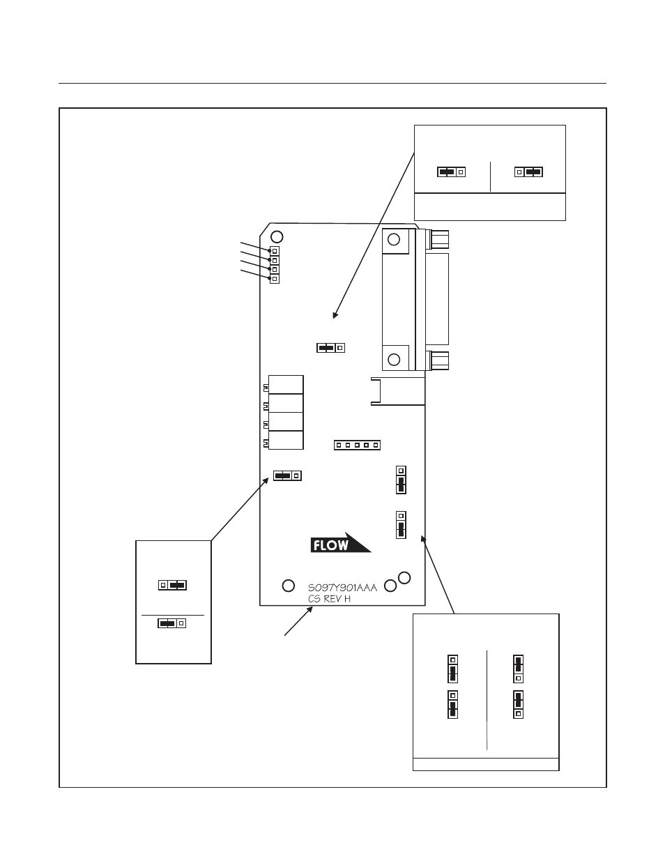
Figure 3-9 Current I/O Version PC Board Jumper Location and Function
B
A
J4
B
J3
A
B
A
J4
N
SS
J2
J7
B
4 - 20 mA
Output
0 - 20 mA
Output
J3
Note: Does not affect voltage output.
Disabled
(Standard)
J2 - RED
SOFT START
Enabled
A
A
A
J7 - GREEN
SETPOINT INPUT SIGNAL TYPE
(Mass Flow Controller only)
CS REV H AND HIGHER.
COMPONENT SIDE SHOWN.
SENSOR
CONNECTOR
R3
R2
R1
R4
VALVE
CONNECTOR
CIRCUIT COMMON TP4
LINEARITY VOLTAGE TP2
VALVE VOLTAGE TP3
TEST POINTS:
SENSOR VOLTAGE TP1
(Multiplied by +100)
A
B
A
J4
B
J3
A
ANTICIPATE
LINEARITY
SPAN
ZERO
ADJUSTMENT POTENTIOMETERS:
0 - 5 VOLTS
4 - 20 mA
J3 & J4 - BLUE
CURRENT OUTPUT RANGE
NOTE:
The 5V Reference is always enabled
and is available on Pin 11.
N
SS
N
SS
- QMBC (52 pages)
- SolidSense II (28 pages)
- SLA7810/20 (36 pages)
- SLA5810/20 (50 pages)
- SLA5840 (46 pages)
- SLA7840 (40 pages)
- 5866E (65 pages)
- IPS122 2 Indicating Pressure Switches" (18 pages)
- IPT122 2 Indicating Pressure Transmitters" (22 pages)
- 8601 (20 pages)
- PTI Metal Seal Mass Flow Controller w/Real-Time Flow Error Detection & Advanced Diagnostics (82 pages)
- SLA5800 Series (76 pages)
- 5800S Series (50 pages)
- 4800 Series (50 pages)
- 5851EM (62 pages)
- 5850E (64 pages)
- 5851E (64 pages)
- 5860E (46 pages)
- 5861E (44 pages)
- 5850i (62 pages)
- 5851i (62 pages)
- 5860i (48 pages)
- 5861i (48 pages)
- 5881/91 (40 pages)
- GF40 (78 pages)
- SLAMf Series (76 pages)
- Mfi Series (82 pages)
- 0254 (124 pages)
- 0260 (14 pages)
- CMC Series (36 pages)
- XacTorr CMX45 (64 pages)
- MT3809G (78 pages)
- MT3809E (72 pages)
- MT3810 (66 pages)
- 3600 Series (56 pages)
- 3750 (64 pages)
- Control Valve (16 pages)
- GT1000 (52 pages)
- 1100 Series (52 pages)
- 1307 (18 pages)
- 1358 (44 pages)
- 1350 (46 pages)
- 1250 (2 pages)
- FC8800 Series (48 pages)