Brooks – Brooks Instrument 5850EM User Manual
Page 33
3-9
Brooks
®
Models 5964, 5850EM
Section 3 Operation
Installation and Operation Manual
X-TMF-5964-5850EM-MFC-eng
Part Number: 541B121AHG
November, 2008
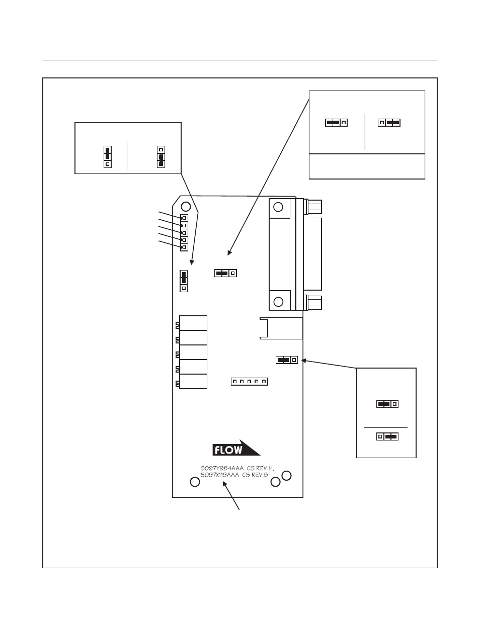
Figure 3-7 Enhanced Response 15 Pin D-Connector PC Board Jumper Location and Function
R9
RESPONSE
R6
ANTICIPATE
LINEARITY
SPAN
ZERO
R12
R1
R4
ADJUSTMENT POTENTIOMETERS:
J3
J2
J1
Disabled
(Standard)
J2 - RED
SOFT START
Enabled
Valve Drive
(15 Volts)
External
Valve
Return
J3 - BLACK
VALVE DRIVE JUMPER
SENSOR
CONNECTOR
VALVE
CONNECTOR
A
A
B
B
- Error
A
B
+ Error
J1 - GREEN
LINEARITY JUMPER
TEST POINTS:
CIRCUIT COMMON TP4
LINEARITY VOLTAGE TP2
VALVE VOLTAGE TP3
SENSOR VOLTAGE (-) TP1
SENSOR VOLTAGE (+) TP0
NOTE:
The 5V Reference is always enabled
and is available on Pin 11.
CS REV H (984) & B (119).
COMPONENT SIDE SHOWN.
See also other documents in the category Brooks Instrument Hardware:
- QMBC (52 pages)
- SolidSense II (28 pages)
- SLA7810/20 (36 pages)
- SLA5810/20 (50 pages)
- SLA5840 (46 pages)
- SLA7840 (40 pages)
- 5866E (65 pages)
- IPS122 2 Indicating Pressure Switches" (18 pages)
- IPT122 2 Indicating Pressure Transmitters" (22 pages)
- 8601 (20 pages)
- PTI Metal Seal Mass Flow Controller w/Real-Time Flow Error Detection & Advanced Diagnostics (82 pages)
- SLA5800 Series (76 pages)
- 5800S Series (50 pages)
- 4800 Series (50 pages)
- 5851EM (62 pages)
- 5850E (64 pages)
- 5851E (64 pages)
- 5860E (46 pages)
- 5861E (44 pages)
- 5850i (62 pages)
- 5851i (62 pages)
- 5860i (48 pages)
- 5861i (48 pages)
- 5881/91 (40 pages)
- GF40 (78 pages)
- SLAMf Series (76 pages)
- Mfi Series (82 pages)
- 0254 (124 pages)
- 0260 (14 pages)
- CMC Series (36 pages)
- XacTorr CMX45 (64 pages)
- MT3809G (78 pages)
- MT3809E (72 pages)
- MT3810 (66 pages)
- 3600 Series (56 pages)
- 3750 (64 pages)
- Control Valve (16 pages)
- GT1000 (52 pages)
- 1100 Series (52 pages)
- 1307 (18 pages)
- 1358 (44 pages)
- 1350 (46 pages)
- 1250 (2 pages)
- FC8800 Series (48 pages)