Brooks, R3 r2 r1 r4 – Brooks Instrument 5850EM User Manual
Page 34
3-10
Brooks
®
Models 5964, 5850EM
Section 3 Operation
Installation and Operation Manual
X-TMF-5964-5850EM-MFC-eng
Part Number: 541B121AHG
November, 2008
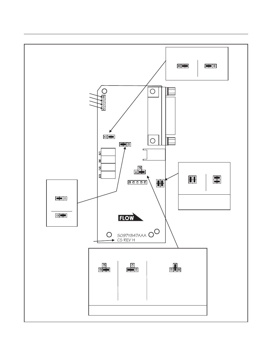
Figure 3-8 Standard Response 15 Pin D-Connector PC Board Jumper Location and Function
N
SS
J2
J3
J4
51
NC
J7
Normally
Closed
Normally
Open
NOTE:
Normally open valves are
identified by a label on the
solenoid cover.
NOTE:
The 5V reference is always enabled and is available on Pin 11.
J4 & J1 - BLUE
VALVE FUNCTION
Disabled
(Standard)
J2 - RED
SOFT START
Enabled
Disabled
(Standard)
Enabled
J7 - GREEN
REMOTE TRANSDUCER INPUT
CS REV H AND HIGHER.
COMPONENT SIDE SHOWN.
Valve Drive.
(30 Volts)
External Valve Return.
Use where Pin 3 is connected
to Power Supply Common at
the Power Supply for 15 Volt
Valve Drive or where Pin 3
is connected to +15 Volts
at the Power Supply for
30 Volt Valve Drive.
Valve Drive.
(15 Volts)
J3 - BLACK
VALVE DRIVE JUMPER
SENSOR
CONNECTOR
ANTICIPATE
LINEARITY
SPAN
ZERO
R3
R2
R1
R4
VALVE
CONNECTOR
50
NO
CIRCUIT COMMON TP4
LINEARITY VOLTAGE TP2
VALVE VOLTAGE TP3
TEST POINTS:
SENSOR VOLTAGE TP1
(Multiplied by -100)
J1
ADJUSTMENT POTENTIOMETERS: