Brooks – Brooks Instrument 5850EM User Manual
Page 21
2-7
Brooks
®
Models 5964, 5850EM
Section 2 Installation
Installation and Operation Manual
X-TMF-5964-5850EM-MFC-eng
Part Number: 541B121AHG
November, 2008
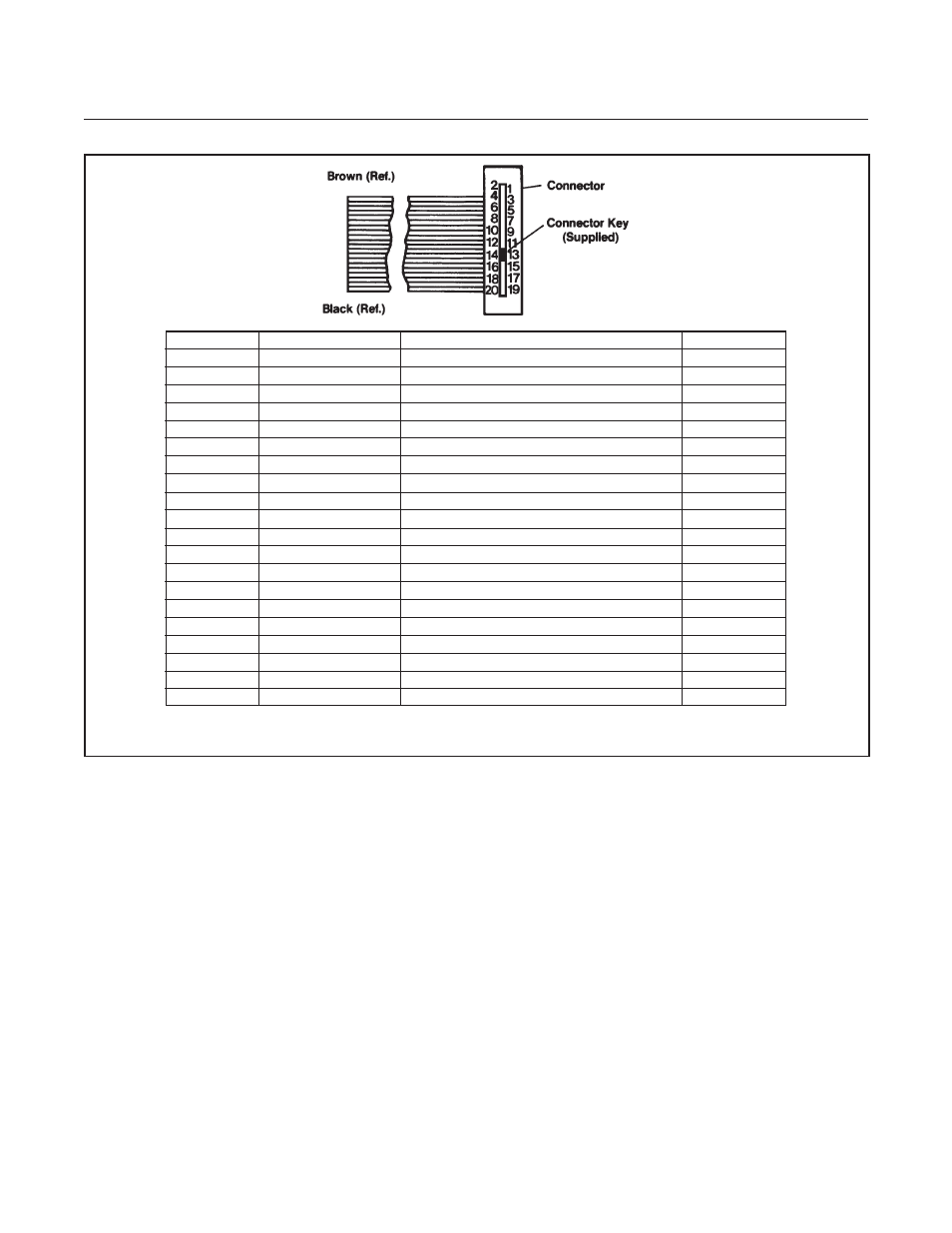
Figure 2-2 20 Pin Card Edge Connector Ribbon Cable Hookup Diagram
PCB No.
Connector Pin No.
Function
Color Code
1
1
Chassis Ground
Brown
A
2
Command Input
Red
2
3
0-5 V Signal Common*
Orange
B
4
Command Common
Yellow
3
5
0-5 V Signal Output
Green
C
6
Supply Common
Blue
4
7
+15 Vdc Supply
Violet
D
8
Valve test Point
Gray
5
9
Not Used**
White
E
10
Not Used
Black
6
11
Not Used
Brown
F
12
-15 Vdc Input
Red
7
13
Slot
Orange
H
14
Slot
Yellow
8
15
Not Used
Green
J
16
Not Used
Blue
9
17
Valve Override
Violet
K
18
Not Used
Gray
10
19
+5 V Reference Output or Valve Return***
White
L
20
Valve Off
Black
*This Pin is used for Valve Common on Unit replacement PC board.
**Jumper Selectable Remote Transducer input on standard response PC board only. Refer to Figure 3-6.
***Jumper Selectable - Refer to Figure 3-5 or 3-6.
- QMBC (52 pages)
- SolidSense II (28 pages)
- SLA7810/20 (36 pages)
- SLA5810/20 (50 pages)
- SLA5840 (46 pages)
- SLA7840 (40 pages)
- 5866E (65 pages)
- IPS122 2 Indicating Pressure Switches" (18 pages)
- IPT122 2 Indicating Pressure Transmitters" (22 pages)
- 8601 (20 pages)
- PTI Metal Seal Mass Flow Controller w/Real-Time Flow Error Detection & Advanced Diagnostics (82 pages)
- SLA5800 Series (76 pages)
- 5800S Series (50 pages)
- 4800 Series (50 pages)
- 5851EM (62 pages)
- 5850E (64 pages)
- 5851E (64 pages)
- 5860E (46 pages)
- 5861E (44 pages)
- 5850i (62 pages)
- 5851i (62 pages)
- 5860i (48 pages)
- 5861i (48 pages)
- 5881/91 (40 pages)
- GF40 (78 pages)
- SLAMf Series (76 pages)
- Mfi Series (82 pages)
- 0254 (124 pages)
- 0260 (14 pages)
- CMC Series (36 pages)
- XacTorr CMX45 (64 pages)
- MT3809G (78 pages)
- MT3809E (72 pages)
- MT3810 (66 pages)
- 3600 Series (56 pages)
- 3750 (64 pages)
- Control Valve (16 pages)
- GT1000 (52 pages)
- 1100 Series (52 pages)
- 1307 (18 pages)
- 1358 (44 pages)
- 1350 (46 pages)
- 1250 (2 pages)
- FC8800 Series (48 pages)