Caution, Brooks, R3 r2 r1 r4 – Brooks Instrument 5850EM User Manual
Page 32
3-8
Brooks
®
Models 5964, 5850EM
Section 3 Operation
Installation and Operation Manual
X-TMF-5964-5850EM-MFC-eng
Part Number: 541B121AHG
November, 2008
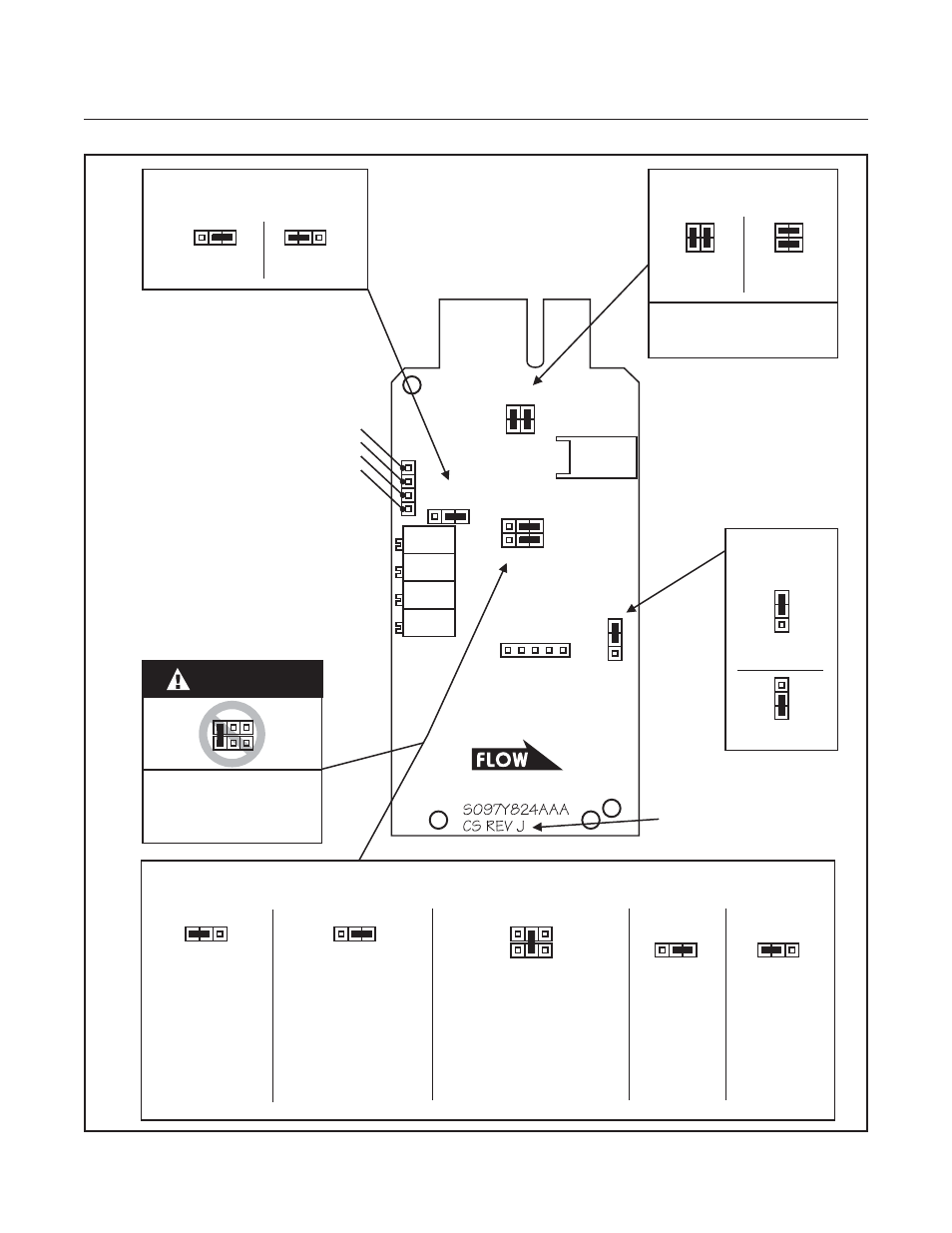
Figure 3-6 Standard Response 20 Pin Card Edge PC Board Jumper Location and Function
ADJUSTMENT POTENTIOMETERS:
Normally
Closed
Normally
Open
J8
J8 - YELLOW
5 VOLT REFERENCE & PIN 10 FUNCTION
CS REV J AND HIGHER.
COMPONENT SIDE SHOWN.
J8
5V Ref. enabled
on Pin 10.
J8
Pin 10 is Connected
to Circuit Common.
5V Ref. Disabled.
(Standard)
J3
Valve Drive
(30 Volts)
J3
External Valve Return. Use
where Pin 10 is connected
to Power Supply Common at
the Power Supply for 15 Volt
Valve Drive or where Pin 10
is connected to +15 Volts
at the Power Supply for
30 Volt Valve Drive.
5V Ref. Disabled.
Disabled
(Standard)
NOTE:
Normally open valves are
identified by a label on the
solenoid cover.
Disabled
(Standard)
J3
Enabled
Valve Drive
(15 Volts)
J7 - GREEN
REMOTE TRANSDUCER INPUT
J3 - BLACK
VALVE DRIVE
J2 - RED
SOFT START
CIRCUIT COMMON TP4
N
J3
N
J2
Enabled
SS
NC
J4
J8
J4 & J1 - BLUE
VALVE FUNCTION
SENSOR
CONNECTOR
NO
R
ANTICIPATE
LINEARITY
SPAN
ZERO
R3
R2
R1
R4
LINEARITY VOLTAGE TP2
VALVE TEST TP3
TEST POINTS:
SENSOR VOLTAGE TP1
(Multiplied by -100)
VALVE
CONNECTOR
J7
J1
J8
Do not place a jumper
between J8 and J3 as
shown above.
Permanent damage
to the board will result.
J3
CAUTION