Brooks – Brooks Instrument 5850EM User Manual
Page 44
3-20
Brooks
®
Models 5964, 5850EM
Section 3 Operation
Installation and Operation Manual
X-TMF-5964-5850EM-MFC-eng
Part Number: 541B121AHG
November, 2008
Calibration Procedure for the Standard Response and Current I/O
PC Board (4 Adjustment Potentiometers)
a. With the controller installed in an unpressurized gas line, apply power
and allow approximately 45 minutes for warm-up. During the warm-up,
adjustment, and calibration check procedures, do not allow the control
valve to drift when gas flow is not present. This situation is not a normal
operating mode and will cause abnormal heat-up of the control valve.
With this abnormally warm valve, the meter will be difficult to calibrate.
This situation can be prevented by switching a normally closed valve to
valve override closed or a normally open valve to valve override open
when there is no gas flow.
b. Rough adjust the anticipate potentiometer with 20 clockwise full turns.
Then, adjust the anticipate potentiometer with 10 counterclockwise
turns to center the potentiometer. This will provide a rough adjustment
of this circuit and make the flow more stable for calibration.
c. Connect the DVM positive lead to the 0-5 Volt signal output, (Pin 3 Card
Edge, Pin 2 D-Connector) and the negative lead to TP4 (circuit com-
mon). Adjust the zero potentiometer for an output of zero mV ±2 mV.
d. Apply pressure to the system and insure that the zero signal repeats
within 2 mV of the voltage set in Step c above. If the zero does not
repeat, check for leakage.
Note: Controllers supplied with all metal or Teflon valve seats do not
provide tight shut-off. A 0-8% leak-through is typical. For metal or Teflon
seat controllers, close a downstream shut-off valve and observe the
flow signal.
e. Set the command potentiometer for 100% of flow (5.000 V). Connect
the DVM positive lead to TP2 (linearity voltage) and the negative lead to
TP4 (circuit common). Adjust the linearity potentiometer for an output of
0.0 V (zero volts).
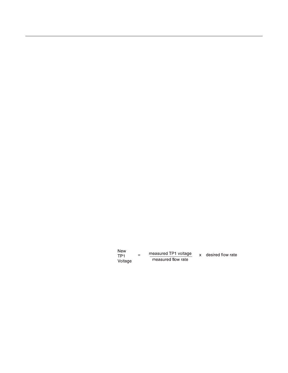
f. Connect the DVM positive lead to TP1 (-100x sensor voltage) and the
negative lead to TP4 (circuit common). The command potentiometer
should still be set at 100% flow (5.000 V). Measure the flow rate using
suitable volumetric calibration equipment. To adjust the controller to the
proper full scale flow, calculate a new TP1 voltage using the following
equation:
Adjust the span potentiometer until the voltage at TP1 is equal to the
value calculated above. Recheck the flow rate after the flow is stable (at
least two minutes). Repeat this check and adjustment procedure until
the measured flow rate is within 1% of the desired flow rate.
Note: The voltage at TP1 is -100 times the output voltage (+100 times
for Current I/O Version) of the sensor. This voltage can range from -1.2
to -12 Volts, however, it is recommended that this voltage stay between
-2.0 and -9.0 Volts for proper operation. If the recommended voltage
range exceeds the desired range, accuracy and/or signal stability may
not be achieved. If one of the limits is reached, check the orifice and
restrictor sizing procedures given in Sections 4-6 and 4-7 respectively.