Brooks – Brooks Instrument 5850EM User Manual
Page 20
2-6
Brooks
®
Models 5964, 5850EM
Section 2 Installation
Installation and Operation Manual
X-TMF-5964-5850EM-MFC-eng
Part Number: 541B121AHG
November, 2008
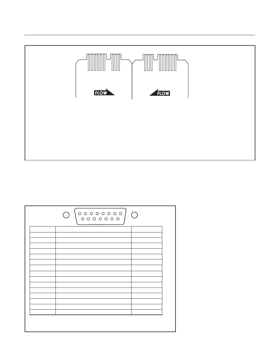
Pin No.
Function
Color Code
1
Command Common
Black
2
0-5 Volt Signal Output
White
3
Not Used/External Valve Return*
Red
4
Valve Off
Green
5
+15 Vdc Supply
Orange
6
-15 Vdc Supply
Blue
7
Valve Test Point/Purge
Wht/Blk
8
Command Input
Red/Blk
9
Supply Common
Grn/Blk
10
0-5 Volt Signal Common
Org/Blk
11
+5 Volt Reference Output
Blu/Blk
12
Valve Override
Blk/Wht
13
Not Used
Red/Wht
14
Chassis Ground
Grn/Wht
15
Not Used**
Blu/Wht
*Jumper Selectable - Refer to Figure 3-7 or 3-8.
**Jumper Selectable -Remote Transducer input on standard response PC board only.
Refer to Figure 3-8.
*
This pin is used for Valve Common on Unit replacement PC Board.
** Remote Transducer In on 3 second response PCB only. Refer to Figure 3-6.
*** Jumper selectable. Refer to Figure 3-5 or 3-6.
SLOT
1
10
9
8
6
SLOT
5
4
3
2
L
A
B
C
D
Component Side
of PC Board
E
F
J
K
Non-Component Side
of PC Board
Figure 2-1 Card Edge Connector
Chassis Ground 1
A Command Input
Flow Signal Common* 2
B Command Common
Flow Signal Output 3
C Supply Common
+15 Vdc Supply 4
D Valve Test Point
Not Used** 5
E Not Used
Not Used 6
F -15Vdc Supply
Slot 7
H Slot
Not Used 8
J Not Used
Valve Override 9
K Not Used
5V Ref. or Valve Return or Not Used***10 L Valve Off
Figure 2-3 D-Connector Shielded Cable Hookup Diagram - Voltage I/O Versions
1
15
9
8